本文主要复述一遍实验过程:
做实验前要先看拓扑和要求
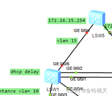
拓扑图和要求如下:
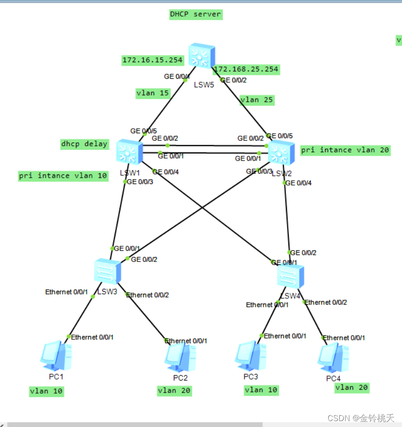
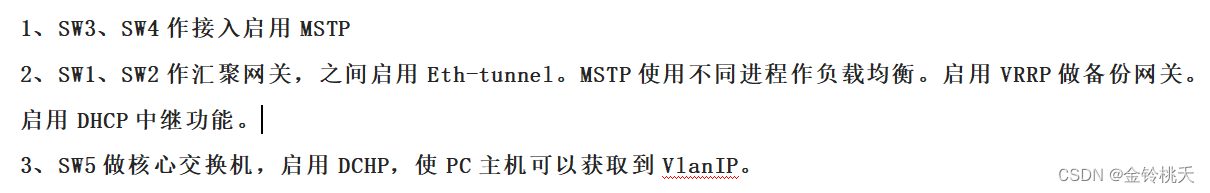
看完要求直接开始实验:
本实验PC机开启DHCP获取IP地址,故PC机不用配置IP地址:
首先,我们先从接入交换机开始配置:
SW3和SW4配置一样,举其中一个例子就OK!!!
接入层比较简单:
1、配置vlan,PC1为Vlan10,PC2为Vlan20
2、连接PC机端为access口,连接汇聚端为trunk口
3、配置MSTP
补充一点:
边缘端口:连接交换机连接下游的PC的接口
stp edged-port enable
边缘端口配置bpdu的保护
stp bpdu-protection
vlan batch 10 20  //可以通过vlan batch 10 20 直接创建多个Vlan

interface Ethernet0/0/1
port link-type access
port default vlan 10
stp edged-port enable


interface Ethernet0/0/2
port link-type access
port default vlan 20
stp edged-port enable

interface GigabitEthernet0/0/1
port link-type trunk
port trunk allow-pass vlan 10 20

interface GigabitEthernet0/0/2
port link-type trunk
port trunk allow-pass vlan 10 20


stp bpdu-protection//注意不是在接口下
开启MSTP
同时根据要求2,不同进程负载均衡
stp mode mstp

stp region-configuration
 region-name NP
 revision-level 1
 instance 10 vlan 10
 instance 20 vlan 20
 active region-configuration
接下来看汇聚层:
SW1和SW2:讲一下SW1的配置,SW参考SW1
不要忘记开启DHCP:dhcp enable
汇聚层配置相比接入层多
1、创建Vlan
vlan batch 10 15 20 25

interface GigabitEthernet0/0/3
 port link-type trunk
 port trunk allow-pass vlan 10 20

interface GigabitEthernet0/0/4
 port link-type trunk
 port trunk allow-pass vlan 10 20

interface GigabitEthernet0/0/5
 port link-type access
 port default vlan 15
 stp disable


interface Vlanif15
ip address 172.16.15.100 255.255.255.02、Eth-Trunk
interface Eth-Trunk12
port link-type trunk
port trunk allow-pass vlan 10 20


interface GigabitEthernet0/0/1
eth-trunk 12

interface GigabitEthernet0/0/2
eth-trunk 12
3、MSTP
stp mode mstp

stp region-configuration
region-name NP
revision-level 1
instance 10 vlan 10
instance 20 vlan 20
active region-configuration
设置进程的主备根
SW1:
stp instance 10 root primary
stp instance 20 root secondary
SW2:
stp instance 20 root primary
stp instance 10 root secondary
stp instance 10 root primary
stp instance 20 root secondary4、VRRP
interface Vlanif10
 ip address 172.16.10.100 255.255.255.0
 vrrp vrid 10 virtual-ip 172.16.10.254
 vrrp vrid 10 priority 105
 vrrp vrid 10 track interface GigabitEthernet0/0/5
 dhcp select relay   //DHCP relay中继
 dhcp relay server-ip 172.16.15.254

interface Vlanif20
 ip address 172.16.20.101 255.255.255.0
 vrrp vrid 20 virtual-ip 172.16.20.254
 dhcp select relay    //DHCP relay中继
 dhcp relay server-ip 172.16.15.254
5、OSPF
ospf 10 router-id 1.1.1.1
 area 0.0.0.0
  network 172.16.10.0 0.0.0.255
  network 172.16.15.0 0.0.0.255
  network 172.16.20.0 0.0.0.255
配置SW5:
不要忘记开启DHCP:dhcp enable
vlan batch 15 25

interface GigabitEthernet0/0/1
 port link-type access
 port default vlan 15
 stp disable   //关闭stp


interface GigabitEthernet0/0/2
 port link-type access
 port default vlan 25
 stp disable   //关闭stp

创建一个环回口
int Loopback 0
ip  address 5.5.5.5 24


interface Vlanif15
 ip address 172.16.15.254 255.255.255.0
 dhcp select global  //开启全局地址池

interface Vlanif25
 ip address 172.16.25.254 255.255.255.0
 dhcp select global  //开启全局地址池
配置IP地址池
ip pool 10
 gateway-list 172.16.10.254
 network 172.16.10.0 mask 255.255.255.0
 dns-list 114.114.114.114
#
ip pool 20
 gateway-list 172.16.20.254
 network 172.16.20.0 mask 255.255.255.0
 dns-list 114.114.114.114
OSPF:
ospf 10 router-id 5.5.5.5
area 0.0.0.0
network 172.16.15.0 0.0.0.255
network 172.16.25.0 0.0.0.255
network 172.16.51.100 0.0.0.0
network 5.5.5.5 0.0.0.0 //宣告环回口
配置完成!!!
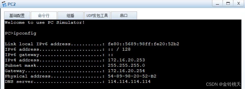
测试一下获取IP地址情况!
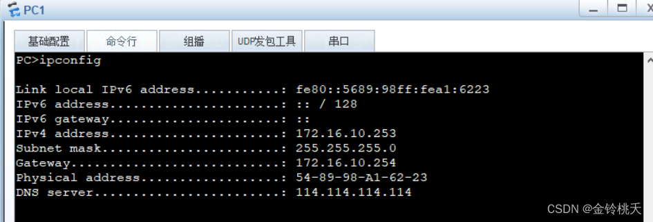
PC1 ping PC2
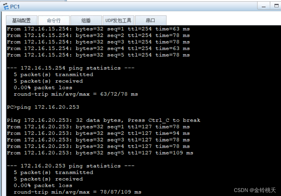
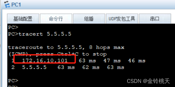
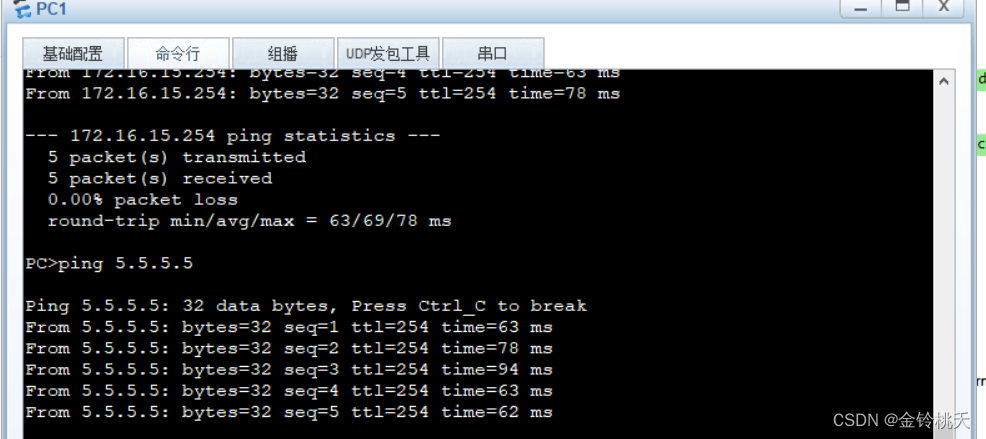
测试SW5环回口地址5.5.5.5
通过Tracert追踪可以发现PC1和PC2走的路径不一样,实现负载均衡
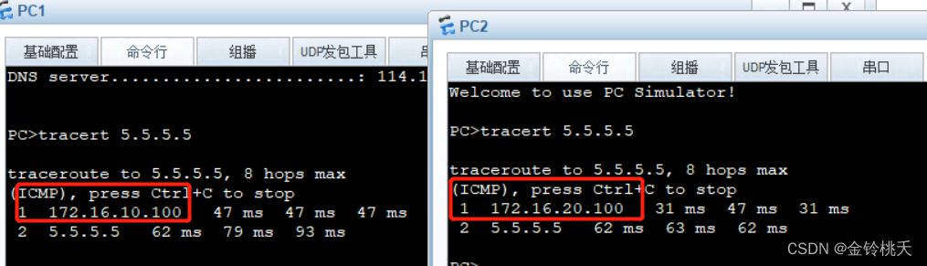
当然通过配置VRRP,当SW1连接SW5的线断开,PC1数据将走向SW2去往SW5
此时PC1数据走的是SW2