单片机学习!
目录
一、USART配置函数
1.1 USART_DeInit函数
void USART_DeInit(USART_TypeDef* USARTx);
USART_DeInit函数将外设 USARTx 寄存器重设为缺省值。
1.2 USART_Init函数
void USART_Init(USART_TypeDef* USARTx, USART_InitTypeDef* USART_InitStruct);
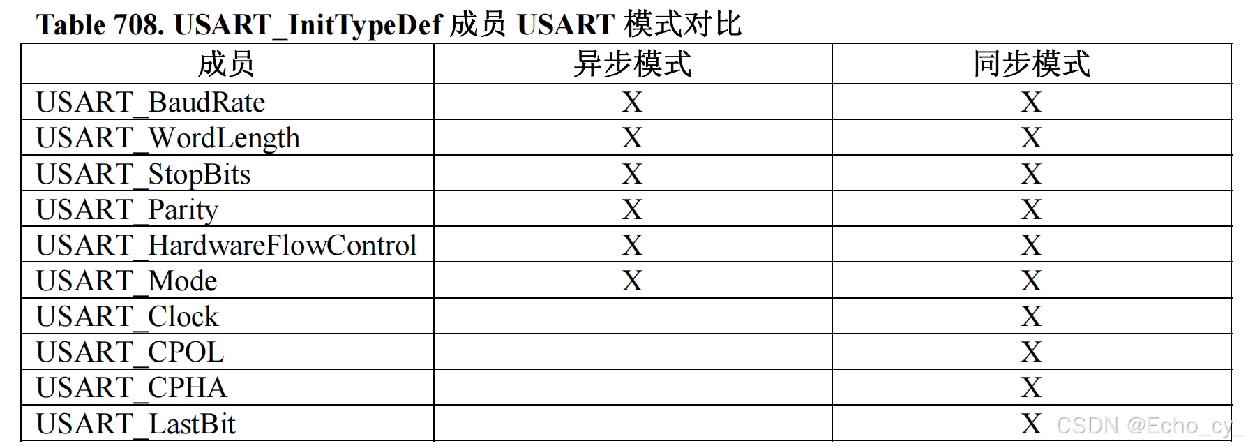
USART_Init函数根据 USART_InitStruct 中指定的参数初始化外设 USARTx 寄存器。
USART_BaudRate
该成员设置了 USART 传输的波特率,波特率可以由以下公式计算:
IntegerDivider = ((APBClock) / (16 * (USART_InitStruct->USART_BaudRate)))
FractionalDivider = ((IntegerDivider - ((u32) IntegerDivider)) * 16) + 0.5
USART_WordLength
USART_WordLength 提示了在一个帧中传输或者接收到的数据位数。
USART_StopBits
USART_StopBits 定义了发送的停止位数目。
USART_Parity
USART_Parity 定义了奇偶模式。
注意:奇偶校验一旦使能,在发送数据的 MSB 位插入经计算的奇偶位(字长 9 位时的第 9 位,字长 8 位时的第 8 位)。
USART_HardwareFlowControl
USART_HardwareFlowControl 指定了硬件流控制模式使能还是失能。
USART_Mode
USART_Mode 指定了使能或者失能发送和接收模式。
USART_CLOCK
USART_CLOCK 提示了 USART 时钟使能还是失能。
USART_CPOL
USART_CPOL 指定了下 SLCK 引脚上时钟输出的极性。
USART_CPHA
USART_CPHA 指定了下 SLCK 引脚上时钟输出的相位,和 CPOL 位一起配合来产生用户希望的时钟/数据的采样关系。
USART_LastBit
USART_LastBit 来控制是否在同步模式下,在 SCLK 引脚上输出最后发送的那个数据字 (MSB)对应的时钟脉冲。
1.3 USART_StructInit函数
void USART_StructInit(USART_InitTypeDef* USART_InitStruct);
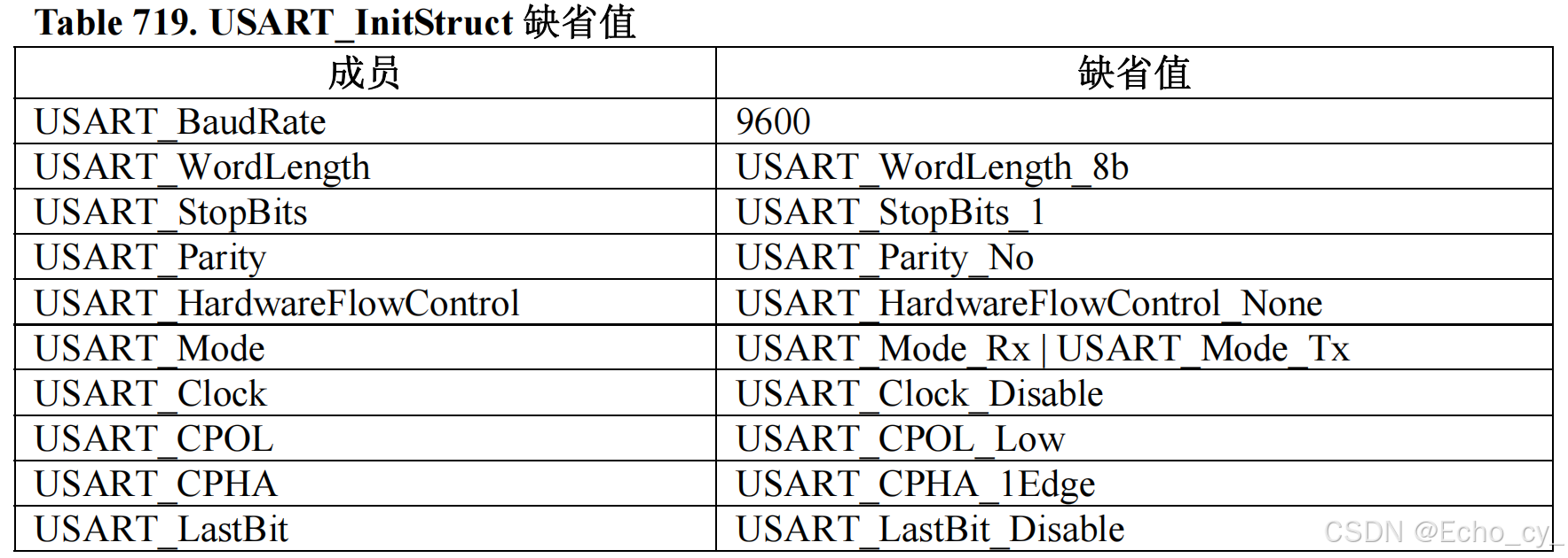
USART_StructInit函数把 USART_InitStruct 中的每一个参数按缺省值填入。
USART_InitStruct各个成员的缺省值:
二、配置同步时钟输出函数
以下两个函数用来配置时钟输出的,包括时钟是不是要输出,时钟的极性相位等参数。因为参数也比较多,所以也是用结构体这种方式来配置的。需要时钟输出时可以考虑使用这两个函数。
2.1 USART_ClockInit函数
void USART_ClockInit(USART_TypeDef* USARTx, USART_ClockInitTypeDef* USART_ClockInitStruct);
源代码:
/**
  * @brief  Initializes the USARTx peripheral Clock according to the
  *          specified parameters in the USART_ClockInitStruct .
  * @param  USARTx: where x can be 1, 2, 3 to select the USART peripheral.
  * @param  USART_ClockInitStruct: pointer to a USART_ClockInitTypeDef
  *         structure that contains the configuration information for the specified
  *         USART peripheral.
  * @note The Smart Card and Synchronous modes are not available for UART4 and UART5.
  * @retval None
  */
void USART_ClockInit(USART_TypeDef* USARTx, USART_ClockInitTypeDef* USART_ClockInitStruct)
{
  uint32_t tmpreg = 0x00;
  /* Check the parameters */
  assert_param(IS_USART_123_PERIPH(USARTx));
  assert_param(IS_USART_CLOCK(USART_ClockInitStruct->USART_Clock));
  assert_param(IS_USART_CPOL(USART_ClockInitStruct->USART_CPOL));
  assert_param(IS_USART_CPHA(USART_ClockInitStruct->USART_CPHA));
  assert_param(IS_USART_LASTBIT(USART_ClockInitStruct->USART_LastBit));

/*---------------------------- USART CR2 Configuration -----------------------*/
  tmpreg = USARTx->CR2;
  /* Clear CLKEN, CPOL, CPHA and LBCL bits */
  tmpreg &= CR2_CLOCK_CLEAR_Mask;
  /* Configure the USART Clock, CPOL, CPHA and LastBit ------------*/
  /* Set CLKEN bit according to USART_Clock value */
  /* Set CPOL bit according to USART_CPOL value */
  /* Set CPHA bit according to USART_CPHA value */
  /* Set LBCL bit according to USART_LastBit value */
  tmpreg |= (uint32_t)USART_ClockInitStruct->USART_Clock | USART_ClockInitStruct->USART_CPOL |
                 USART_ClockInitStruct->USART_CPHA | USART_ClockInitStruct->USART_LastBit;
  /* Write to USART CR2 */
  USARTx->CR2 = (uint16_t)tmpreg;
}
2.2 USART_ClockStructInit函数
void USART_ClockStructInit(USART_ClockInitTypeDef* USART_ClockInitStruct);
源代码:
/**
  * @brief  Fills each USART_ClockInitStruct member with its default value.
  * @param  USART_ClockInitStruct: pointer to a USART_ClockInitTypeDef
  *         structure which will be initialized.
  * @retval None
  */
void USART_ClockStructInit(USART_ClockInitTypeDef* USART_ClockInitStruct)
{
  /* USART_ClockInitStruct members default value */
  USART_ClockInitStruct->USART_Clock = USART_Clock_Disable;
  USART_ClockInitStruct->USART_CPOL = USART_CPOL_Low;
  USART_ClockInitStruct->USART_CPHA = USART_CPHA_1Edge;
  USART_ClockInitStruct->USART_LastBit = USART_LastBit_Disable;
}
三、USART的外设与中断函数
3.1 USART_Cmd函数
void USART_Cmd(USART_TypeDef* USARTx, FunctionalState NewState);
3.2 USART_ITConfig函数
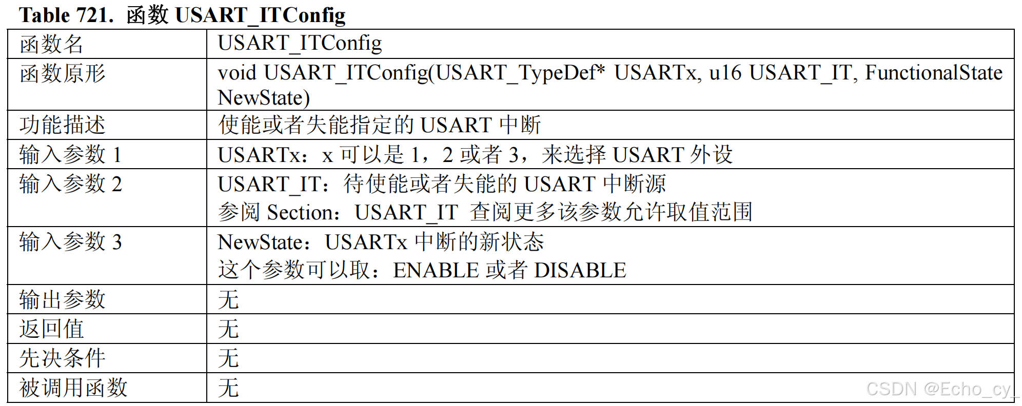
void USART_ITConfig(USART_TypeDef* USARTx, uint16_t USART_IT, FunctionalState NewState);
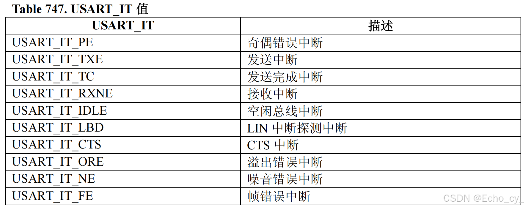
USART_IT
输入参数 USART_IT 使能或者失能 USART 的中断。
四、USART的DMA触发函数
4.1 USART_DMACmd函数
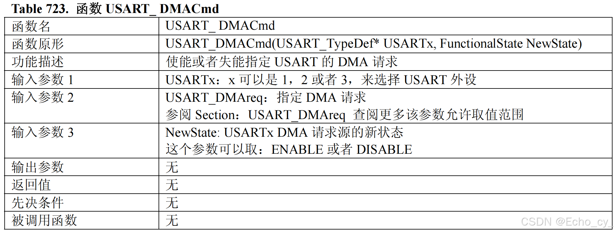
void USART_DMACmd(USART_TypeDef* USARTx, uint16_t USART_DMAReq, FunctionalState NewState);
USART_DMACmd函数可以开启USART到DMA的触发通道,需要使用DMA时要用到这个函数。
USART_DMAreq
USART_DMAreq选择待使能或者失能的DMA请求。
五、发送/接收数据函数
SendData发送数据;ReceiveData接收数据,以下两个函数在接收和发送数据时会用到。
- SendData就是写DR寄存器;
- ReceiveData就是读DR寄存器。
DR寄存器内部有4个寄存器,控制发送与接收,执行细节可以参考上一篇博文。这里程序上函数使用就非常简单了,写DR就是发送,读DR就是接收。至于怎么产生波形,怎么判断输入,软件一概不管。
5.1 USART_SendData函数
void USART_SendData(USART_TypeDef* USARTx, uint16_t Data);
5.2 USART_ReceiveData函数
uint16_t USART_ReceiveData(USART_TypeDef* USARTx);
六、标志位相关函数
6.1 USART_GetFlagStatus函数
FlagStatus USART_GetFlagStatus(USART_TypeDef* USARTx, uint16_t USART_FLAG);
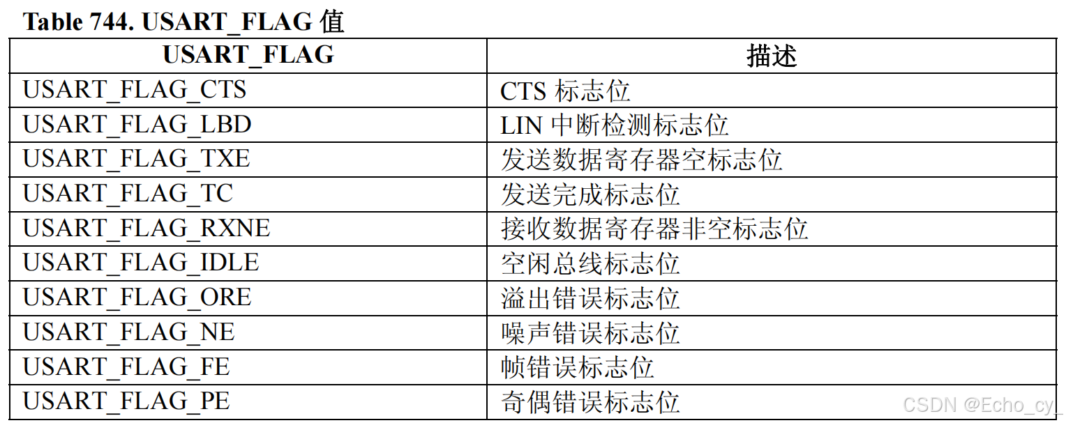
USART_FLAG
下表给出了所有可以被函数USART_ GetFlagStatus检查的标志位列表
6.2 USART_ClearFlag函数
void USART_ClearFlag(USART_TypeDef* USARTx, uint16_t USART_FLAG);
6.3 USART_GetITStatus函数
ITStatus USART_GetITStatus(USART_TypeDef* USARTx, uint16_t USART_IT);
USART_IT
下表给出了所有可以被函数USART_ GetITStatus检查的中断标志位列表
6.4 USART_ClearITPendingBit函数
void USART_ClearITPendingBit(USART_TypeDef* USARTx, uint16_t USART_IT);


