0. 论文及代码
参考论文:SensorX2car: Sensors-to-car calibration for autonomous driving in road
scenarios
参考代码:lidar2car
1. 标定原理
①在车辆行驶中,lidar 可以观测到地面,我们通过提取点云中的地面并拟合平面方程,根据平面方程法向量与(0,0,1)之间的旋转可以得到 lidar 和车身之间的 roll/pitch;
②求解(0,0,0)点到提取地面的距离再减去轮胎半径得到 lidar 到车身后轴中心的高度;
③ 得到 roll/pitch 后将点云与地面对齐,然后通过点云配准(或者SLAM算法)得到 lidar 的 DR,根据此 DR 轨迹 进行 B 样条曲线拟合并求导得到车体坐标系下的航向角变化
④上述航向角与 DR 中 lidar 的 航向作差,即 lidar 系和车体系之间的 yaw,至此 lidar in vehicle 的 roll/pitch/height/yaw 全部标定成功。
2. 拟合平面
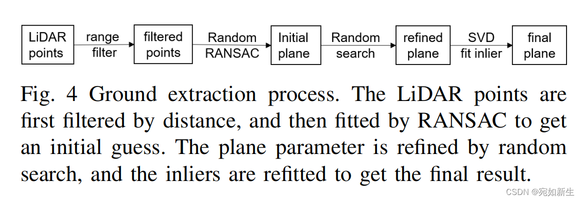
拟合平面的pipline如下:首先就是为了减少计算量,对激光雷达观测到的点云进行滤波操作。然后利用ransac算法拟合出initial plane,接着通过微调平面参数使其能覆盖更多的“地面内点”。最后根据“地面内点”通过SVD分解方法得到平面的法向量。
    /* @brief: plane params: normal=[a,b,c]; intercept= d;
    	ax + by + cz + d = 0;
     */
struct PlaneParam {
    PlaneParam() {}
    PlaneParam(const Eigen::Vector3d& n, double i) : normal(n), intercept(i) {}
    Eigen::Vector3d normal;
    double intercept;
};

/* @brief: ground extraction object */
 class GroundExtractor {
 public:
    GroundExtractor() = default;
    ~GroundExtractor() = default;

    /* @brief: ground extraction using random ransac algorithm,
     * aim at the slaver lidar*/
    bool RandomRansacFitting(const PointCloudPtr in_cloud,
                             PointCloudPtr g_cloud,
                             PointCloudPtr ng_cloud,
                             PlaneParam * plane);

 private:
    size_t RandIndex(size_t range); // Random point selection
    bool CalArea(const PointType& p1,
                 const PointType& p2,
                 const PointType& p3,
                 double* area); // Make sure the three points you pick fit into a triangle
    // In ransac, normal vectors are calculated based on randomly selected planes
    bool FittingPlane(PointCloudPtr in_cloud, PlaneParam *plane);
    // Solving plane normal vector by SVD decomposition
    bool FittingPlaneMesh(const PointCloudPtr in_cloud, PlaneParam *plane);
    // Fine-tune the plane parameters to include more inliers
    bool RandomSearchPlane(const PointCloudPtr in_cloud, PlaneParam &best_plane, int &max_inlier_points,
                           double n1_scope, double n2_scope, double n3_scope, double i_scope, int iteration_times);

 private:
 	/* @breif ransac params
 	*/
    const int rr_iter_times_ = 5;
    const int rr_max_rand_iters_ = 500;
    const double rr_gpoints_rate_ = 0.4;
    const double rr_min_area_thre_ = 0.25;
    const double rr_fit_dist_thre_ = 0.1;

};
3. 标定roll/pitch/height
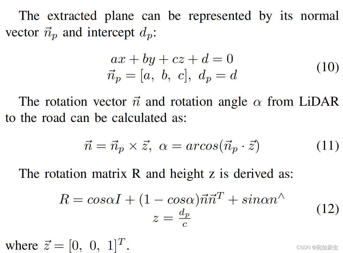
得到平面方程之后,我们可以计算激光雷达原点到拟合平面的距离,此距离就是lidar到地面的高度。同时,我们可以根据平面法向量和向量[0,0,1]计算地面与lidar的旋转(roll和pitch)。
注意: 这一步只能得到roll,pitch。
        Eigen::Vector3d master_z(0, 0, 1);
        Eigen::Vector3d rot_axis = master_gplane.normal.cross(master_z);
        rot_axis.normalize();
        double alpha = -std::acos(master_gplane.normal.dot(master_z));

        // extrinsic: plane to master lidar
        Eigen::Matrix3d R_mp;
        R_mp = Eigen::AngleAxisd(alpha, rot_axis);
        Eigen::Vector3d t_mp(0, 0,
                         -master_gplane.intercept / master_gplane.normal(2));
        Eigen::Matrix4d T_pm = Util::GetMatrix(t_mp, R_mp).inverse();
        double roll = Util::GetRoll(T_pm);
        double pitch = Util::GetPitch(T_pm);
/* avoid using it: matrix.block<3, 3>(0, 0).eulerAngles(0, 1, 2)[0];*/
    static double GetRoll(const Eigen::Matrix4d& matrix) {
        Eigen::Matrix3d R = matrix.block<3, 3>(0, 0);

        Eigen::Vector3d n = R.col(0);
        Eigen::Vector3d o = R.col(1);
        Eigen::Vector3d a = R.col(2);
        double y = atan2(n(1), n(0));
        double r = atan2(a(0) * sin(y) - a(1) * cos(y),
                         -o(0) * sin(y) + o(1) * cos(y));
        return r;
    }
    static double GetPitch(const Eigen::Matrix4d& matrix) {
        Eigen::Matrix3d R = matrix.block<3, 3>(0, 0);
        Eigen::Vector3d n = R.col(0);
        double y = atan2(n(1), n(0));
        double p = atan2(-n(2), n(0) * cos(y) + n(1) * sin(y));

        return p;
    }
4. 标定yaw
得到激光雷达到地面的roll和pitch之后,就可以讲激光点云与地面对齐,然后我们使用SLAM算法或者点云配准方法,得到lidar的DR轨迹[
X
i
,
Y
i
,
Y
a
w
i
X_i, Y_i, Yaw_i
Xi,Yi,Yawi]。
另一方面,我们可以根据上面的[
X
i
,
Y
i
X_i, Y_i
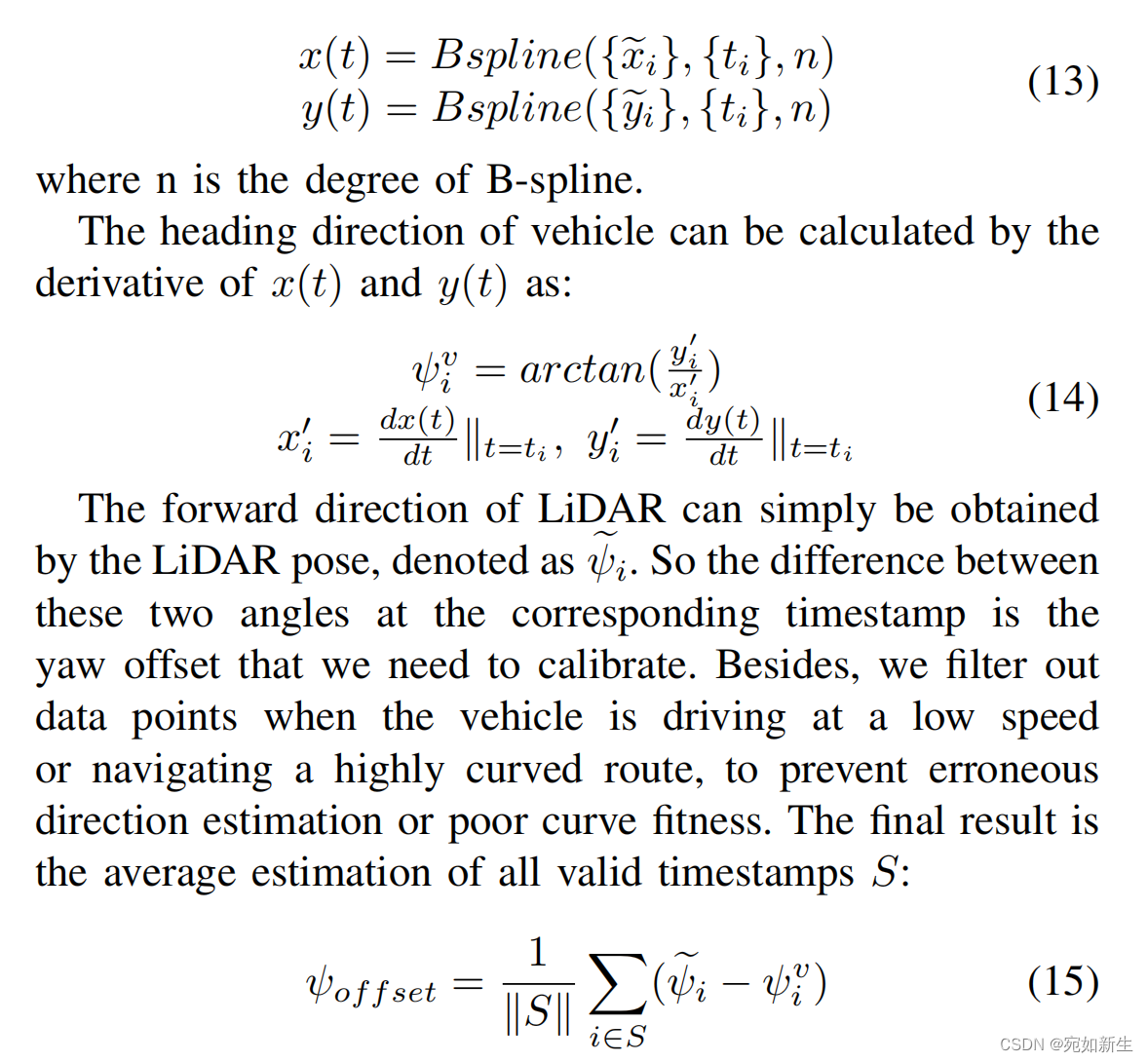
Xi,Yi]进行B_spline拟合出一条轨迹。对此轨迹每个时刻求偏导,可以得到车辆各时刻的航向变化。
已知lidar的航向变化以及车辆的航向变化,他们两个应该是拥有一个航向偏差同步变化的。于是两者之差即是lidar与vehicle的航向外参。
bool YawCalib::GetYawSegs(const DataTable &sample_x, const DataTable &sample_y, std::vector<DataTable> &samples_yaw){

    BSpline bspline_x = BSpline::Builder(sample_x).degree(bspine_degree_).smoothing(BSpline::Smoothing::PSPLINE).alpha(0.03).build();
    BSpline bspline_y = BSpline::Builder(sample_y).degree(bspine_degree_).smoothing(BSpline::Smoothing::PSPLINE).alpha(0.03).build();

    int discarded_nums = int(pose_num_ * 0.05);
    DataTable tmp_yaw;
    int last_t = 0;
    double last_yaw = 0;

    for (int i = discarded_nums; i < pose_num_ - discarded_nums; i += time_gap_)
    {
        DenseVector t(1);
        t(0) = i;
        double dx = bspline_x.evalJacobian(t)(0, 0);
        double dy = bspline_y.evalJacobian(t)(0, 0);
        double ddx = bspline_x.evalHessian(t)(0, 0);
        double ddy = bspline_y.evalHessian(t)(0, 0);
        double cur_x = fabs(ddx) / pow(1 + dx * dx, 1.5);
        double cur_y = fabs(ddy) / pow(1 + dy * dy, 1.5);

        // delete unmoving points
        if (dx * dx + dy * dy < 1e-3)
            continue;
        // detele points with large curvature
        if (cur_x > 0.015 || cur_y > 0.015)
            continue;

        double yaw = atan2(dy, dx);
        t(0) = i + bspine_degree_;
        if(tmp_yaw.getNumSamples() != 0 && i - last_t > time_gap_ * 5)
        {
            if(tmp_yaw.getNumSamples() > 20)
            {
                samples_yaw.push_back(tmp_yaw);
            }
            tmp_yaw = DataTable();
        }
        if(tmp_yaw.getNumSamples() != 0 && fabs(yaw - last_yaw) > M_PI){
            if(yaw - last_yaw > M_PI) {
                yaw -= 2 * M_PI;
            }
            else if(yaw - last_yaw < -M_PI) {
                yaw += 2 * M_PI;
            }
        }
        tmp_yaw.addSample(t, yaw);
        last_yaw = yaw;
        last_t = i;
    }
    if(tmp_yaw.getNumSamples() > 20)
    {
        samples_yaw.push_back(tmp_yaw);
    }
    return true;
}
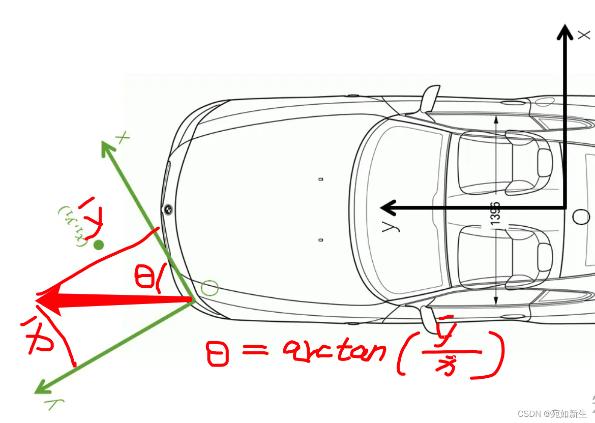
4.1 理解从B_spline拟合的轨迹中得到vehicle航向
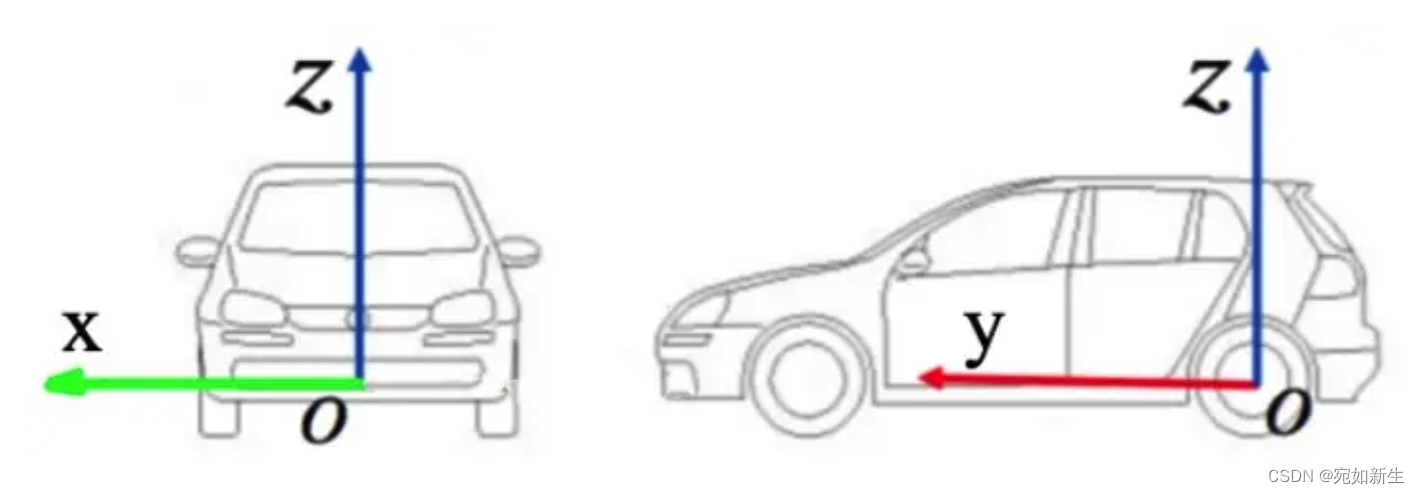
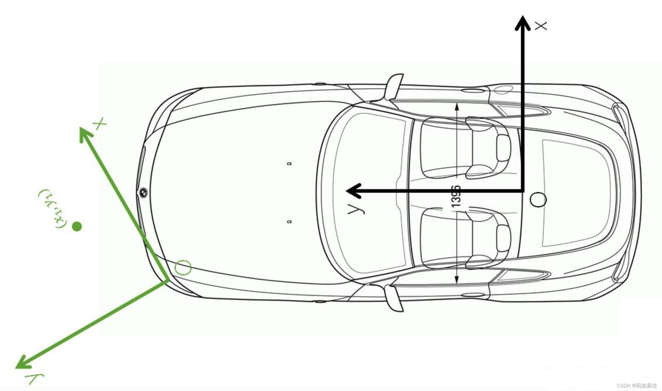
假设车辆坐标系的前向为Y,车辆右侧指向为X,天向为Z;
假设下图中绿色为激光雷达的坐标系。
当车辆直线行驶时,我们通过SLAM算法或者点云匹配算法得到的激光雷达位姿[
X
i
,
Y
i
,
Y
a
w
i
X_i, Y_i, Yaw_i
Xi,Yi,Yawi]中的
Y
a
w
i
=
0
Yaw_i = 0
Yawi=0,但是根据激光雷达位置[
X
i
,
Y
i
X_i, Y_i
Xi,Yi]进行B_spline拟合的曲线求偏导得到的角度表示vehicle的航向在以激光雷达为参考系下的表示,它不为0。
5. 精度
根据工作中的开发情况来看,旋转精度可以达到0.01度(其中yaw角标定依赖SLAM算法或者点云配准精度),高度精度可以达到0.05m。
