一、工程模板
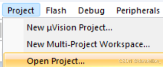
参照第一篇,新建工程目录ProjectMould,将先前打包好的Start,Library和User文件^C^V过来,并在Keil5内完成器件支持包的加载,模块路径的添加和ST配置,即可得到工程模板。
以后建立新项目只需拷贝模板、重命名后,在Keil5内打开即可。
二、点亮主板
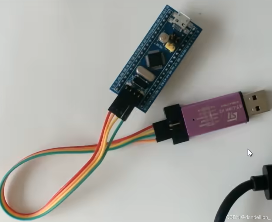
所需器材:STM32最小系统板、ST-Link仿真器、母对母杜邦线4根。
端口接线:
| STM32 | ST-Link |
|---|---|
| GND | GND |
| SWCLK | SWCLK |
| SWIO | SWDIO |
| 3V3 | 3.3V |
正确接入后,PWR端口01灯常亮,PC13端口02灯闪烁,这是芯片内置的初始测试程序。
1. 配置寄存器
该方法需要阅读芯片参考手册,将数字信号转换为八进制传递参数。
#include "stm32f10x.h"

int main(void)
{
	// 配置寄存器点灯
	RCC->APB2ENR = 0x00000010;	// RCC寄存器——APB2外设时钟使能寄存器 -> 开启IO端口C时钟
	GPIOC->CRH = 0x00300000;	// GPIO寄存器——端口配置高寄存器 -> 通用推挽输出模式:最大速度50MHz
	GPIOC->ODR = 0x00002000;	// GPIO寄存器——端口输出数据寄存器 -> PC13端口:高电平(灭)
	//GPIOC->ODR = 0x00000000;	// GPIO寄存器——端口输出数据寄存器 -> PC13端口:低电平(亮)
}
程序编写完成后,F7 + F8编译并载入,就可以实现PC13端口02灯的控制。
2. 调用库函数
该方法形式较为复杂,但代码更具复用性和可读性,下文开始全部使用库函数编程。
#include "stm32f10x.h"

int main(void)
{
	// 外设时钟控制:使能/失能APB2的外设时钟 -> 开启IO端口C时钟
	RCC_APB2PeriphClockCmd(RCC_APB2Periph_GPIOC, ENABLE);

	// 配置结构体参数
	GPIO_InitTypeDef GPIO_InitStructure;
	GPIO_InitStructure.GPIO_Mode = GPIO_Mode_Out_PP;	// 通用推挽输出模式
	GPIO_InitStructure.GPIO_Pin = GPIO_Pin_13;			// PC13引脚
	GPIO_InitStructure.GPIO_Speed = GPIO_Speed_50MHz;	// 最大速度50MHz

	// 初始化端口模式 -> 初始化GPIOC外设时钟
	GPIO_Init(GPIOC, &GPIO_InitStructure);

	// 配置端口电平
	GPIO_SetBits(GPIOC, GPIO_Pin_13);		// 高电平:熄灭
	//GPIO_ResetBits(GPIOC, GPIO_Pin_13);	// 低电平:点亮
}
三、LED
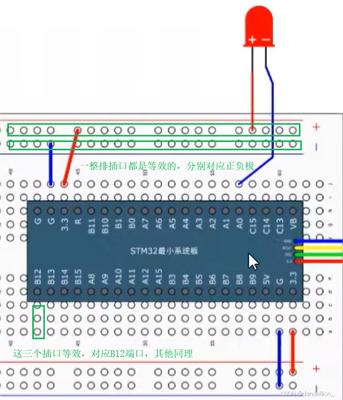
所需器材:STM32最小系统板、ST-LINK仿真器、MB-102面包板、LED(长脚+,短脚-)若干、跳线若干、杜邦线若干。
系统板初次插入面包板会十分困难,建议先用杜邦线探针逐个疏通面包板的插孔,然后在系统板两端交替施力,“跷跷板式”下压,直至完全进入。
1. 闪烁
参照第一篇,将目录Resource\程序源码\STM32Project-无注释版\1-3 Delay函数模块\下的头文件加入System,完成延时函数模块的添加,编译并载入以下代码。
#include "stm32f10x.h"	// 器件模块
#include "Delay.h" 		// 延时模块

// LED闪烁
int main(void)
{
	// 使能/失能APB2的外设时钟 -> 开启IO端口A时钟
	RCC_APB2PeriphClockCmd(RCC_APB2Periph_GPIOA, ENABLE);

	// 配置结构体参数
	GPIO_InitTypeDef GPIO_InitStructure;
	GPIO_InitStructure.GPIO_Mode = GPIO_Mode_Out_PP;	// 通用推挽输出模式
	GPIO_InitStructure.GPIO_Pin = GPIO_Pin_0;			// PA0引脚
	GPIO_InitStructure.GPIO_Speed = GPIO_Speed_50MHz;	// 最大速度50MHz

	// 配置端口模式 -> 初始化GPIOA外设时钟
	GPIO_Init(GPIOA, &GPIO_InitStructure);

	// 配置端口电平
	//GPIO_SetBits(GPIOA, GPIO_Pin_0);		// 高电平:熄灭
	//GPIO_ResetBits(GPIOA, GPIO_Pin_0);	// 低电平:点亮

	// 闪烁:周期200毫秒
	while(1)
	{
		//GPIO_WriteBit(GPIOA, GPIO_Pin_0, Bit_RESET);		// 低电平:点亮
		//Delay_ms(500);
		//GPIO_WriteBit(GPIOA, GPIO_Pin_0, Bit_SET);		// 高电平:熄灭
		//Delay_ms(500);

		GPIO_WriteBit(GPIOA, GPIO_Pin_0, (BitAction)0);		// 低电平:点亮
		Delay_ms(100);
		GPIO_WriteBit(GPIOA, GPIO_Pin_0, (BitAction)1);		// 高电平:熄灭
		Delay_ms(100);
	}
}
2. 流水灯
在A0至A7端口接入LED。
#include "stm32f10x.h"	// 器件模块
#include "Delay.h" 		// 延时模块

// 流水灯
int main(void)
{
	// 使能/失能APB2的外设时钟 -> 开启IO端口A时钟
	RCC_APB2PeriphClockCmd(RCC_APB2Periph_GPIOA, ENABLE);

	// 配置结构体参数
	GPIO_InitTypeDef GPIO_InitStructure;
	GPIO_InitStructure.GPIO_Mode = GPIO_Mode_Out_PP;	// 通用推挽输出模式
	GPIO_InitStructure.GPIO_Pin = GPIO_Pin_All;			// 所有引脚
	//GPIO_InitStructure.GPIO_Pin = GPIO_Pin_0 | GPIO_Pin_1 | GPIO_Pin_2 | GPIO_Pin_3 | GPIO_Pin_4 | GPIO_Pin_5 | GPIO_Pin_6 | GPIO_Pin_7; // PA引脚
	GPIO_InitStructure.GPIO_Speed = GPIO_Speed_50MHz;	// 最大速度50MHz

	// 配置端口模式 -> 初始化GPIOA外设时钟
	GPIO_Init(GPIOA, &GPIO_InitStructure);

	// 延时闪烁:取反 -> 低电平:点亮
	while(1)
	{
		GPIO_Write(GPIOA, ~0x0001);		// A0
		Delay_ms(100);
		GPIO_Write(GPIOA, ~0x0002);		// A1
		Delay_ms(100);
		GPIO_Write(GPIOA, ~0x0004);		// A2
		Delay_ms(100);
		GPIO_Write(GPIOA, ~0x0008);		// A3
		Delay_ms(100);
		GPIO_Write(GPIOA, ~0x0010);		// A4
		Delay_ms(100);
		GPIO_Write(GPIOA, ~0x0020);		// A5
		Delay_ms(100);
		GPIO_Write(GPIOA, ~0x0040);		// A6
		Delay_ms(100);
		GPIO_Write(GPIOA, ~0x0080);		// A7
		Delay_ms(100);
	}
}
四、蜂鸣器
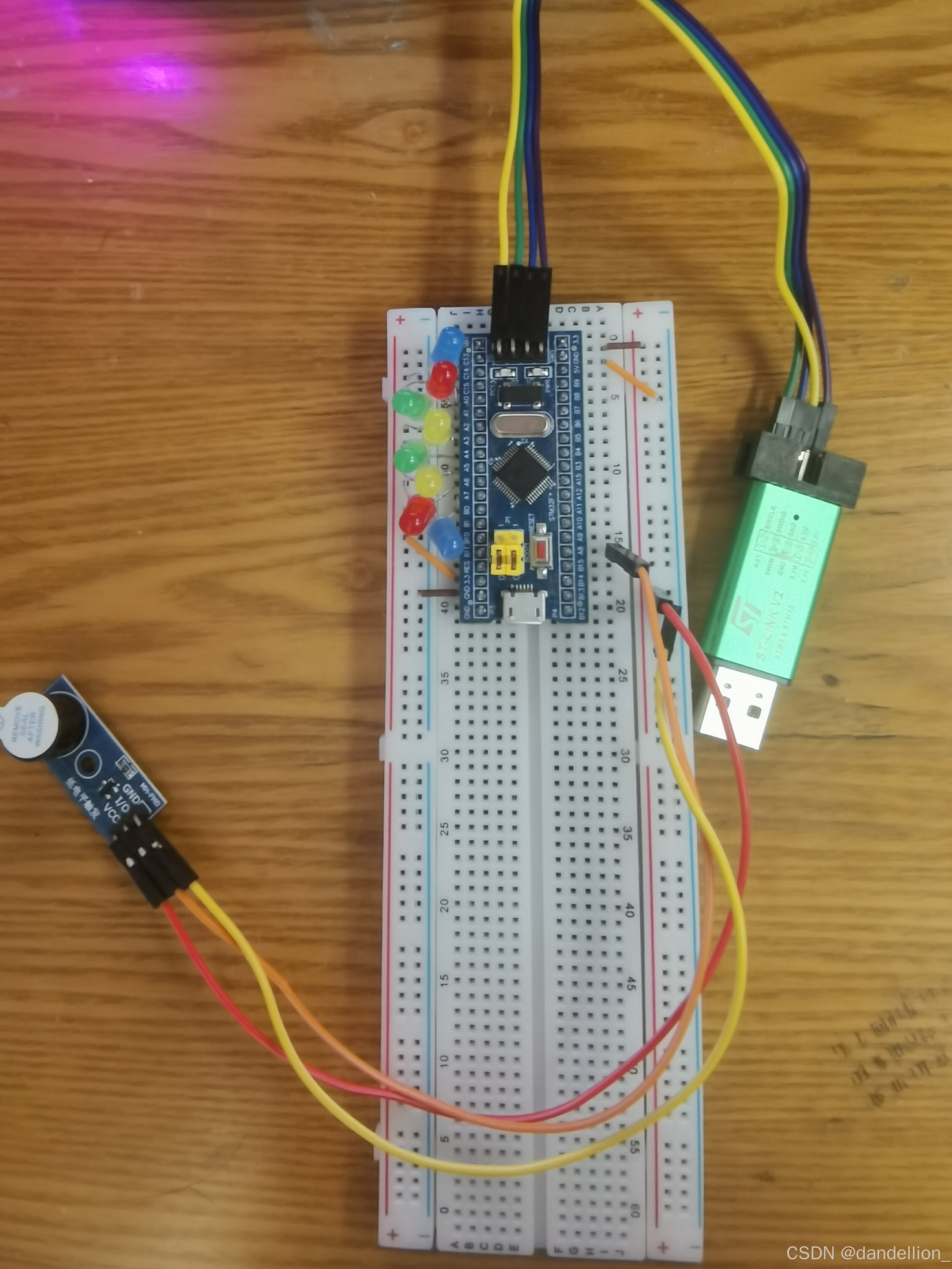
所需器材:STM32最小系统板、ST-LINK仿真器、MB-102面包板、3.3V有源蜂鸣器、跳线若干、公对公/母杜邦线若干。
端口接线:除了A15,B3,B4是JLINK的调试端口,其他端口都可用。
| 蜂鸣器 | 面包板 |
|---|---|
| GND | - |
| I/O | B13 |
| VCC | + |
#include "stm32f10x.h"	// 器件模块
#include "Delay.h" 		// 延时模块

// 蜂鸣器
int main(void)
{
	// 使能/失能APB2的外设时钟 -> 开启IO端口B时钟
	RCC_APB2PeriphClockCmd(RCC_APB2Periph_GPIOB, ENABLE);

	// 配置结构体参数
	GPIO_InitTypeDef GPIO_InitStructure;
	GPIO_InitStructure.GPIO_Mode = GPIO_Mode_Out_PP;	// 通用推挽输出模式
	GPIO_InitStructure.GPIO_Pin = GPIO_Pin_12;			// PB12引脚
	GPIO_InitStructure.GPIO_Speed = GPIO_Speed_50MHz;	// 最大速度50MHz

	// 配置端口模式 -> 初始化GPIOB外设时钟
	GPIO_Init(GPIOB, &GPIO_InitStructure);

	// 手表闹钟
	while(1)
	{
		GPIO_ResetBits(GPIOB, GPIO_Pin_12);	// 低电平:响
		Delay_ms(100);
		GPIO_SetBits(GPIOB, GPIO_Pin_12);
		Delay_ms(100);
		GPIO_ResetBits(GPIOB, GPIO_Pin_12);
		Delay_ms(100);
		GPIO_SetBits(GPIOB, GPIO_Pin_12);
		Delay_ms(700);
	}
}


