简介
网上搜索好多玩GD32 I2C总线的都是用软件GPIO模拟的。有反映硬件I2C不稳定,程序卡死(循环,get flag 那里),于是入手了3件I2C的硬件,空余时间把玩下。走了不少弯路,不过最终还是搞懂,搞通了。嘻嘻~
本次使用的是gd32官网V2.2.0 的demo,参考自带EEPROM的代码进行修改。使用的是I2C1–PB10,11,留意这个stm32的是I2C2了,命名方式gd32的是从0开始的。
硬件I2C配置
把一些共用的代码整合到i2c.c。其他不同硬件区分代入自己的I2C 地址码就可以了,减少代码重复,部分代码如下。
!!!重点,由于本次总共有3个I2C设备地址,i2c.h 里 I2Cx_SLAVE_ADDRESS7 这个定义的8bit地址,试了随便填一个都可以。我理解只是总线初始化使用而已。因为后面使用时读写时,代码里I2C start后,会重传新一次设备地址和(发送/接收)方向,在此处传入要通讯的设备地址就可以了。这样也比较合情理,在总线挂多设备情况
刚开始看demo i2c和at24cxx地址是同一个,走了不少弯路,重新初始化I2C什么的。
i2c_mode_addr_config(I2C1, I2C_I2CMODE_ENABLE, I2C_ADDFORMAT_7BITS, I2Cx_SLAVE_ADDRESS7);
#include "gd32f10x.h"
#include "i2c.h"
#include <stdio.h>

/*!
    \brief      configure the GPIO ports
    \param[in]  none
    \param[out] none
    \retval     none
*/
void gpio_config(void)
{
    /* enable GPIOB clock */
    rcu_periph_clock_enable(RCU_GPIOB);
    /* enable I2C1 clock */
    rcu_periph_clock_enable(RCU_I2C1);

    /* connect PB10 to I2C0_SCL */
    /* connect PB11 to I2C0_SDA */
    gpio_init(GPIOB, GPIO_MODE_AF_OD, GPIO_OSPEED_50MHZ, GPIO_PIN_10 | GPIO_PIN_11);
}

/*!
    \brief      configure the I2C1 interfaces
    \param[in]  none
    \param[out] none
    \retval     none
*/
void i2c_config(void)
{
    /* enable I2C clock */
    rcu_periph_clock_enable(RCU_I2C1);
    /* configure I2C clock */
    i2c_clock_config(I2C1, I2Cx_SPEED, I2C_DTCY_2);
    /* configure I2C address */
    i2c_mode_addr_config(I2C1, I2C_I2CMODE_ENABLE, I2C_ADDFORMAT_7BITS, I2Cx_SLAVE_ADDRESS7);
    /* enable I2C0 */
    i2c_enable(I2C1);
    /* enable acknowledge */
    i2c_ack_config(I2C1, I2C_ACK_ENABLE);
}

//2024-5-21 参考demo修改函数,除地址头外,发送的字符用数组统一收/发。
/*
p_buffer : 要发送的数组
i2c_address :I2C 从设备地址
number_of_byte :要发送的字节长度,多少个Byte字节
*/

/*!
    \brief      read data from the devices
    \param[in]  p_buffer: pointer to the buffer that read form the slave device
		\param[in]	i2c_address: I2C slave device address
    \param[in]  w_address: internal address to start read
    \param[in]  number_of_byte: number of bytes to read
    \param[out] none
    \retval     none

*/
void i2c_read_data(uint8_t* p_buffer, uint8_t i2c_address, uint8_t r_address, uint16_t number_of_byte)
{
    /* wait until I2C bus is idle */
    while(i2c_flag_get(I2C1, I2C_FLAG_I2CBSY));

    if(2 == number_of_byte){
        i2c_ackpos_config(I2C1, I2C_ACKPOS_NEXT);
    }

    /* send a start condition to I2C bus */
    i2c_start_on_bus(I2C1);

    /* wait until SBSEND bit is set */
    while(!i2c_flag_get(I2C1, I2C_FLAG_SBSEND));

    /* send slave address to I2C bus */
    i2c_master_addressing(I2C1, i2c_address, I2C_TRANSMITTER);

    /* wait until ADDSEND bit is set */
    while(!i2c_flag_get(I2C1, I2C_FLAG_ADDSEND));

    /* clear the ADDSEND bit */
    i2c_flag_clear(I2C1, I2C_FLAG_ADDSEND);

    /* wait until the transmit data buffer is empty */
    while(SET != i2c_flag_get(I2C1 , I2C_FLAG_TBE));

    /* enable I2C1*/
    i2c_enable(I2C1);

    /* send the EEPROM's internal address to write to */
    i2c_data_transmit(I2C1, r_address);

    /* wait until BTC bit is set */
    while(!i2c_flag_get(I2C1, I2C_FLAG_BTC));

    /* send a start condition to I2C bus */
    i2c_start_on_bus(I2C1);

    /* wait until SBSEND bit is set */
    while(!i2c_flag_get(I2C1, I2C_FLAG_SBSEND));

    /* send slave address to I2C bus */
    i2c_master_addressing(I2C1, i2c_address, I2C_RECEIVER);

    if(number_of_byte < 3){
        /* disable acknowledge */
        i2c_ack_config(I2C1, I2C_ACK_DISABLE);
    }

    /* wait until ADDSEND bit is set */
    while(!i2c_flag_get(I2C1, I2C_FLAG_ADDSEND));

    /* clear the ADDSEND bit */
    i2c_flag_clear(I2C1, I2C_FLAG_ADDSEND);

    if(1 == number_of_byte){
        /* send a stop condition to I2C bus */
        i2c_stop_on_bus(I2C1);
    }

    /* while there is data to be read */
    while(number_of_byte){
        if(3 == number_of_byte){
            /* wait until BTC bit is set */
            while(!i2c_flag_get(I2C1, I2C_FLAG_BTC));

            /* disable acknowledge */
            i2c_ack_config(I2C1, I2C_ACK_DISABLE);
        }
        if(2 == number_of_byte){
            /* wait until BTC bit is set */
            while(!i2c_flag_get(I2C1, I2C_FLAG_BTC));

            /* send a stop condition to I2C bus */
            i2c_stop_on_bus(I2C1);
        }

        /* wait until the RBNE bit is set and clear it */
        if(i2c_flag_get(I2C1, I2C_FLAG_RBNE)){
            /* read a byte from the EEPROM */
            *p_buffer = i2c_data_receive(I2C1);

            /* point to the next location where the byte read will be saved */
            p_buffer++;

            /* decrement the read bytes counter */
            number_of_byte--;
        }
    }

    /* wait until the stop condition is finished */
    while(I2C_CTL0(I2C1) & 0x0200);

    /* enable acknowledge */
    i2c_ack_config(I2C1, I2C_ACK_ENABLE);

    i2c_ackpos_config(I2C1, I2C_ACKPOS_CURRENT);
}
SSD1306 显示屏
1.OLED屏初始化,整合采用了数组方式。代码是少了,就是哪个参数设置那个功能的就要反查了,感觉还是不太理想。
//OLED 初始化函数组
uint8_t OLED_INIT[]={0xAE,0x00,0x10,0x40,0xB0,0x81,0xFF,0xA1,0xA6,0xA8,0x3F,0xC8,0xD3,0x00,0xD5,0x80,0xD8,0x05,0xD9,0xF1,0xDA,0x12,0xDB,0x30,0x8D,0x14,0xAF};

void oled_init(void)
{
		uint8_t i,n;
		n = sizeof OLED_INIT;
		for(i=0;i<n;i++)
		{
			i2c_2Bytes_write(OLED_ADDRESS,OLED_CMD,OLED_INIT[i]);
		}
}
2.显示也是用了数据方式,更新数据到显示屏的GDDRAM。
//更新GDDRAM数据到显示屏
void oled_refresh(void)
{
	uint8_t x,y;
	for(y=0;y<8;y++)
	{
		i2c_2Bytes_write(OLED_ADDRESS,OLED_CMD,0xB0+y);		//set page start address for page addressing mode
		i2c_2Bytes_write(OLED_ADDRESS,OLED_CMD,0x00);			//set lower column start address for page addressing mode
		i2c_2Bytes_write(OLED_ADDRESS,OLED_CMD,0x10);			//set higher column start address for page addressing mode
		for(x=0;x<128;x++)
		{
			i2c_2Bytes_write(OLED_ADDRESS,OLED_DAT,OLED_GRAM[x][y]);
		}
	}

}
RTC-实时时钟 PCF8563
获取、设置时间代码
#include "pcf8563.h"
#include "i2c.h"
#include <stdio.h>
#include "systick.h"
#include "oled.h"


unsigned char get_time[5];


uint8_t rtc_get_time(uint8_t r_add)
{
		uint8_t time_dat[1];
		i2c_read_data(time_dat,RTC_ADDRESS,r_add,1);
		return time_dat[0];
}

//读取RTC 寄存器 数据
uint8_t time_str[10];

void get_rtc_time(void)
{
		uint8_t time[5];
		time[0] = rtc_get_time(0x02)&0x7F;		//second
		time[1] = rtc_get_time(0x03)&0x7F;		//minute
		time[2] = rtc_get_time(0x04)&0x3F;		//hour
		time[3] = rtc_get_time(0x05)&0x3F;		//day
		time[4] = rtc_get_time(0x07)&0x1F;		//month

//		for(i=0;i<5;i++)
//		{
//			printf("get_time:%0.2X\r\n",time[i]);
//		}

		//BCD转码获取时间信息用于显示。16进制转10进制。
		get_time[0] = (time[0]/16)*10+(time[0]%16);
		get_time[1] = (time[1]/16)*10+(time[1]%16);
		get_time[2] = (time[2]/16)*10+(time[2]%16);
		get_time[3] = (time[3]/16)*10+(time[3]%16);
		get_time[4] = (time[4]/16)*10+(time[4]%16);

		printf("日期:%d月-%d日 时间:%.2d:%.2d:%.2d\r\n",get_time[4],get_time[3],get_time[2],get_time[1],get_time[0]);

		oled_show_string(12,16,"-   time:  :  :",8,1);		//格式 xx/xx time:xx:xx:xx

		sprintf((char*)time_str,"%d",get_time[4]);
		oled_show_string(0,16,time_str,8,1);

		sprintf((char*)time_str,"%d",get_time[3]);
		oled_show_string(18,16,time_str,8,1);

		sprintf((char*)time_str,"%.2d",get_time[2]);
		oled_show_string(66,16,time_str,8,1);

		sprintf((char*)time_str,"%.2d",get_time[1]);
		oled_show_string(84,16,time_str,8,1);

		sprintf((char*)time_str,"%.2d",get_time[0]);
		oled_show_string(102,16,time_str,8,1);
}

uint8_t set_time_data[5] = {0x00,0x00,0x21,0x28,0x05};	//second,minute,hour,day,month 5月28日15时0分0秒
//uint8_t rtc_time_reg[5] = {0x02,0x03,0x04,0x05,0x07};

uint8_t rtc_stop[2] = {0x00,0x20};
uint8_t rtc_start[2] = {0x00,0x00};

void set_rtc_time(void)
{
		i2c_Bytes_write(rtc_stop,RTC_ADDRESS,2);		//clock stop

		i2c_2Bytes_write(RTC_ADDRESS,0x02,set_time_data[0]);
		i2c_2Bytes_write(RTC_ADDRESS,0x03,set_time_data[1]);
		i2c_2Bytes_write(RTC_ADDRESS,0x04,set_time_data[2]);
		i2c_2Bytes_write(RTC_ADDRESS,0x05,set_time_data[3]);
		i2c_2Bytes_write(RTC_ADDRESS,0x07,set_time_data[4]);

		i2c_Bytes_write(rtc_start,RTC_ADDRESS,2);		//clock start
}
SHT30-温湿度传感
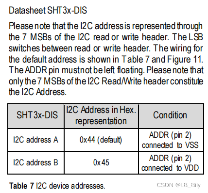
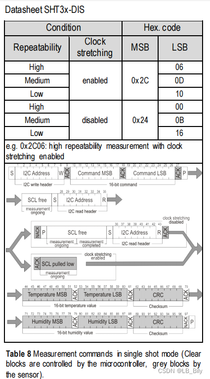
本次采用了单次触发模式测试温湿度。注意 I2C 地址和芯片第二脚电平有对应关系。本次用的0x44。0x44是设备的7bit地址,不是8bit。要移位补上R/W后面1bit。
#include "sht30.h"
#include "i2c.h"
#include <stdio.h>
#include "systick.h"
#include "oled.h"


/*SHT30 状态寄存器的读取命令。The status register contains information on the
operational status of the heater, the alert mode and on
the execution status of the last command and the last
write sequence.
*/

//读取SHT30状态寄存器信息
uint8_t status_buff[3] = {0};
void read_sht30_status(void)
{
	i2c_2Bytes_write(SHT30_ADDRESS,0xF3,0x2D);		// read the status register

	i2c_Bytes_read(status_buff,SHT30_ADDRESS,3);
//	sht30_data_read(status_buff,SHT30_ADDRESS,0xF3,0x2D,3);

	printf("\r\nsht30 status REG_MSB:0x%02X",status_buff[0]);
	printf("\r\nREG_LSB:0x%02X",status_buff[1]);
	printf("\r\nREG_CRC:0x%02X",status_buff[2]);
}

//单次触发 测量并读取温湿度数据,single shot mode
//SHT30 测量温湿度,enable clock stretching,high/medium/low repeatability

//uint8_t H_measurement [2] = {0x2C,0x06};
//uint8_t M_measurement [2] = {0x2C,0x0D};
//uint8_t L_measurement [2] = {0x2C,0x10};

uint8_t measu_data_buff[6] = {0};
uint16_t T_RH[2]={0};

void read_measure_data (void)
{
	uint16_t hum=0,temp=0;
	i2c_2Bytes_write(SHT30_ADDRESS,0x2C,0x10);		// high repeatability measurement with clock stretching enable
	delay_1ms(50);
	i2c_Bytes_read(measu_data_buff,SHT30_ADDRESS,6);		//read the temperature&humidity

//		for(i=0;i<6;i++)
//		{
//			printf("0x%02X \r\n",measu_data_buff[i]);
//
//		}

		//数据提取
		temp = (measu_data_buff[0] << 8) | measu_data_buff[1];
		hum = (measu_data_buff[3] << 8) | measu_data_buff[4];

		T_RH[0] = temp;
		T_RH[1] = hum;
//		printf("\r\n measu_data:0x%04X",T_RH[0]);
//		printf("\r\n measu_data:0x%04X",T_RH[1]);
}

uint8_t str[10];
//uint8_t tempstr[]={0x03,0x03,0x3E,0x41,0x41,0x41};
void show_ht_info(void)
{
		float temp,hum;

		i2c_2Bytes_write(SHT30_ADDRESS,0x30,0xA2);		//soft reset sht30
		delay_1ms(10);
		read_measure_data();

		temp = -45.0f+175.0f*(T_RH[0]/65535.0f);
		hum = 100.0f*(T_RH[1]/65535.0f);

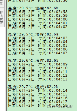
		printf("\r\n温度:%0.1f°C,湿度:%0.1f%%\r\n",temp,hum);

		oled_show_string(0,0,"temp:",8,1);
		oled_show_string(0,8,"hum-:",8,1);

		sprintf((char *)str,"%0.1f",temp);
		oled_show_string(30,0,str,8,1);
		oled_show_string(56,0,"|",8,1);			//修改自定义字符°C

		sprintf((char *)str,"%0.1f",hum);
		oled_show_string(30,8,str,8,1);
		oled_show_string(56,8,"%",8,1);
}
演示视频
gd32d硬件IIC调试
总结
由于是调试,加了不少串口打印信息跟踪代码。
显示屏显示字符串使用了sprintf函数转换成字符。
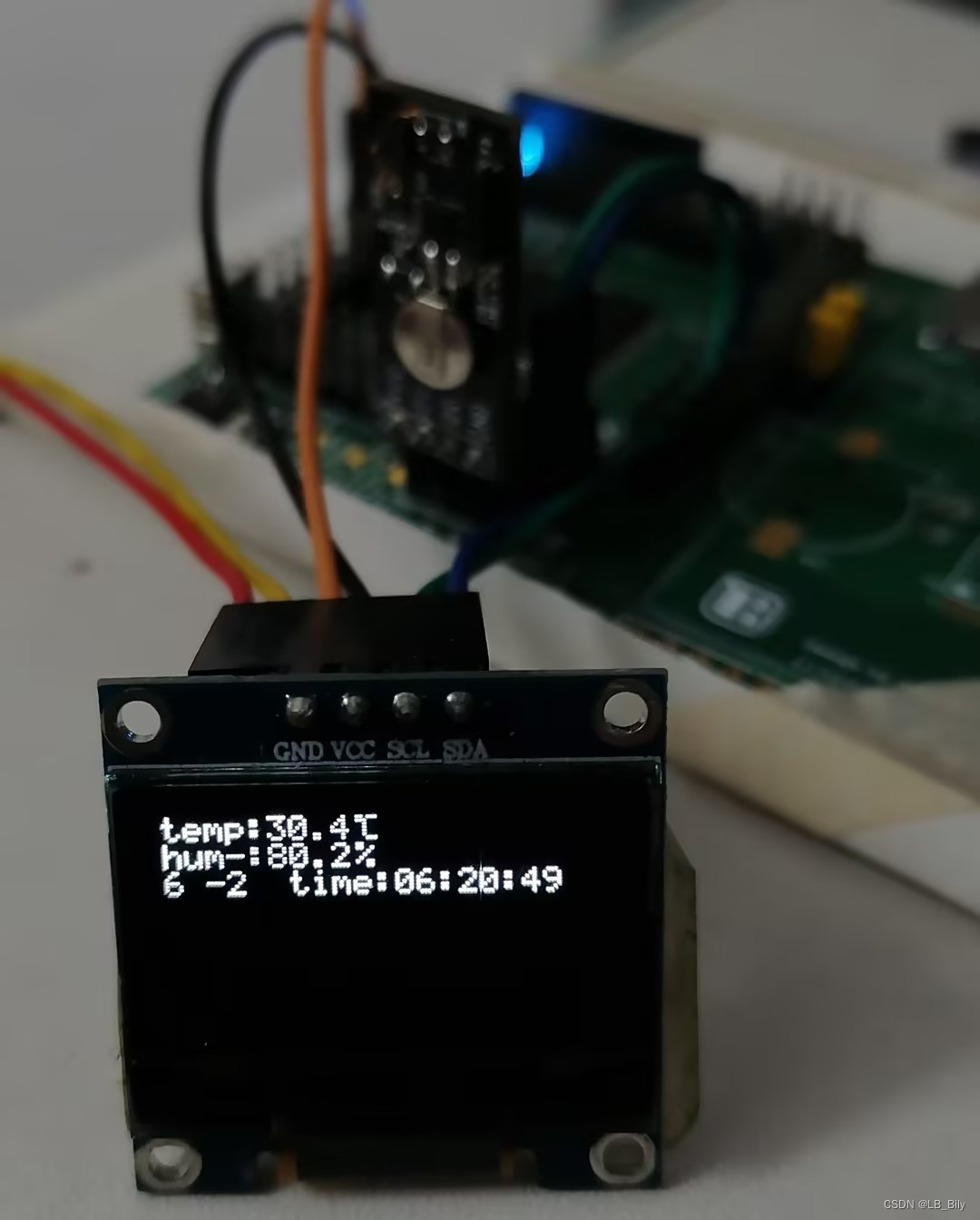
由于摄氏温度符号,末尾自己增加,修改了 oledfont.h 8x6的代码。
例程是每秒刷新一次时间,每5秒刷新一次温湿度信息。
{0x00, 0x1C, 0xA0, 0xA0, 0xA0, 0x7C},// y
{0x00, 0x44, 0x64, 0x54, 0x4C, 0x44},// z  : 122-32
{0x14, 0x14, 0x14, 0x14, 0x14, 0x14},// horiz lines
{0x03, 0x03, 0x3E, 0x41, 0x41, 0x41},// |->°C bily add 20240602


