外参描述了相机在世界坐标系中的位置和朝向,即它将世界坐标转换为相机坐标的几何变换。具体来说,外参包括一个 旋转矩阵 R R R 和一个 平移向量 t t t,它们共同构成了将世界坐标变换到相机坐标系的刚体变换。
1. 外参矩阵的定义
外参矩阵通常表示为一个
3
×
4
3 \times 4
3×4 的矩阵,形式如下:
[
R
t
]
\begin{bmatrix} R & t \end{bmatrix}
[Rt]
其中:
- R R R 是一个 3 × 3 3 \times 3 3×3 的旋转矩阵,它描述了相机的朝向(姿态)。
- t t t 是一个 3 × 1 3 \times 1 3×1 的平移向量,它描述了相机相对于世界坐标系的平移。
该矩阵的作用是将世界坐标系下的点 P w = ( X w , Y w , Z w ) ⊤ \mathbf{P}_w = (X_w, Y_w, Z_w)^\top Pw=(Xw,Yw,Zw)⊤ 转换为相机坐标系下的点 P c = ( X c , Y c , Z c ) ⊤ \mathbf{P}_c = (X_c, Y_c, Z_c)^\top Pc=(Xc,Yc,Zc)⊤:
P c = R P w + t \mathbf{P}_c = R \mathbf{P}_w + t Pc=RPw+t
可以将这个过程写成齐次坐标形式,方便描述:
[ X c Y c Z c 1 ] = [ R t 0 1 ] [ X w Y w Z w 1 ] \begin{equation} \begin{bmatrix} X_c \\ Y_c \\ Z_c \\ 1 \end{bmatrix} = \begin{bmatrix} R & t \\ 0 & 1 \end{bmatrix} \begin{bmatrix} X_w \\ Y_w \\ Z_w \\ 1 \end{bmatrix} \end{equation} XcYcZc1 =[R0t1] XwYwZw1
这其中的 [ R t 0 1 ] \begin{bmatrix} R & t \\ 0 & 1 \end{bmatrix} [R0t1] 矩阵就是外参矩阵的扩展形式(齐次变换矩阵)。
2. 相机姿态推导
我们关心的是如何从外参矩阵 [ R t ] \begin{bmatrix} R & t \end{bmatrix} [Rt] 中推导出相机在世界坐标系中的姿态,即旋转和位置。
2.1 相机的位置
相机的世界坐标位置
C
\mathbf{C}
C 是通过将相机坐标原点逆变换到世界坐标系中获得的。相机坐标系中的原点在相机坐标下是
P
c
=
(
0
,
0
,
0
)
⊤
\mathbf{P}_c = (0, 0, 0)^\top
Pc=(0,0,0)⊤,因此有:
R
C
+
t
=
0
R \mathbf{C} + t = 0
RC+t=0
解得相机在世界坐标系中的位置为:
C
=
−
R
−
1
t
\mathbf{C} = -R^{-1} t
C=−R−1t
由于旋转矩阵
R
R
R 是正交矩阵,所以
R
−
1
=
R
⊤
R^{-1} = R^\top
R−1=R⊤,因此相机位置可以表示为:
C
=
−
R
⊤
t
\mathbf{C} = -R^\top t
C=−R⊤t
2.2 相机的朝向(姿态)
相机的姿态由旋转矩阵 R R R 表示,它将世界坐标系中的方向向量旋转到相机坐标系中。具体来说,旋转矩阵的列向量表示世界坐标系中基向量在相机坐标系中的方向。
因此, R R R 描述了相机相对于世界坐标系的旋转。如果想得到相机在世界坐标系中的姿态,可以求 R R R 的转置矩阵 R ⊤ R^\top R⊤,因为 R R R 将世界坐标系变换到相机坐标系,而 R ⊤ R^\top R⊤ 则是反向变换,即从相机坐标系变回世界坐标系的旋转。
3. 具体步骤总结
要从外参推导相机在世界坐标系中的姿态,步骤如下:
-
提取旋转矩阵 R R R:从外参矩阵 P = [ R t ] P = \begin{bmatrix} R & t \end{bmatrix} P=[Rt] 中提取前 3 × 3 3 \times 3 3×3 的部分 R R R,这就是旋转矩阵,表示相机的朝向。
-
提取平移向量 t t t:从外参矩阵提取最后的 3 × 1 3 \times 1 3×1 部分 t t t,表示相机的平移。
-
计算相机位置 C \mathbf{C} C:通过公式 C = − R ⊤ t \mathbf{C} = -R^\top t C=−R⊤t 得到相机的世界坐标系中的位置。
-
相机的朝向:旋转矩阵 R R R 直接描述了世界坐标系如何转换到相机坐标系。如果需要相机在世界坐标系中的姿态(即从相机坐标系转换到世界坐标系),使用 R ⊤ R^\top R⊤ 作为反向旋转矩阵。
4. 示例
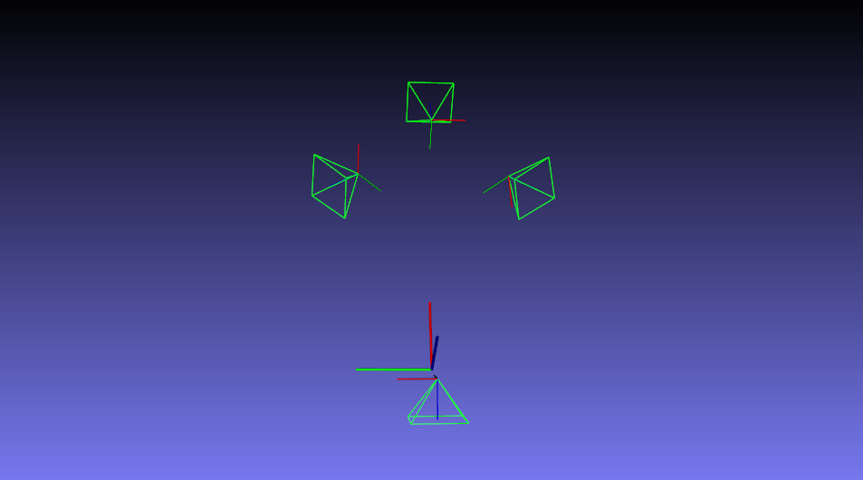
把前后左右四个相机用opencv viz模块绘制出来。
TEST(Demo, DemoOfCamera)
{
    Sentinel_Config sentinel_config = GetDefaultConfig();

    Camera2World front_camera2world(sentinel_config.front_yaml_path);
    Camera2World rear_camera2world(sentinel_config.rear_yaml_path);
    Camera2World left_camera2world(sentinel_config.left_yaml_path);
    Camera2World right_camera2world(sentinel_config.right_yaml_path);


    // visualize camera
    cv::viz::Viz3d window("Coordinate Frame");

    auto visualize_function = [&](Camera2World &camera2world, std::string widget_name)
    {

        cv::Matx33d K = camera2world.camera_param.para_K;
        cv::Matx33d R = camera2world.camera_param.Rcw;
        cv::Vec3d T = camera2world.camera_param.Tcw;

        cv::Vec3d camera_position = -R.t() * T;

        cv::viz::WCameraPosition cam(0.5); // Coordinate axes
        cv::viz::WCameraPosition cam_frustum(K, 0.5, cv::viz::Color::green()); // Camera frustum

        window.showWidget(widget_name, cam);
        window.showWidget(widget_name+" frustum", cam_frustum);

        // set the viewer pose
        cv::Affine3d cam_pose(R.t(), camera_position);
        window.setWidgetPose(widget_name, cam_pose);
        window.setWidgetPose(widget_name+" frustum", cam_pose);
    };


    visualize_function(front_camera2world, "Front Camera");
    visualize_function(rear_camera2world, "Rear Camera");
    visualize_function(left_camera2world, "Left Camera");
    visualize_function(right_camera2world, "Right Camera");

    // visualize world
    cv::viz::WCoordinateSystem world_coor(1.0);
    window.showWidget("World", world_coor);

    window.spin();

}
camera_position
