近期进行了verilog编程语言的复习和回顾,顺便把网站上的题刷了一遍,个别题的答案解析也是参考网上的资源。虽然网上也有很多人做了详细的答案解析,有的博主讲解得详细透彻,比如:
https://blog.csdn.net/reborn_lee/category_9533452.html
https://blog.csdn.net/wangkai_2019/article/details/106100728#1.1%C2%A0Getting%20Started(Step%20one)
但是本人还是想简单总结、记录、分享一下自己的学习记录与心得,毕竟别人的东西是别人的。自己确定下来以后要往这个方向发展,就得一点一点的积累,先把简单的事情做好。给自己打点鸡血吧。哈哈!
希望能对初学者带来一定的帮助!
HDLBits 网站主要为练习Verilog 语言的使用和基本逻辑电路的设计。网站提供了在线编程环境,用户根据题目编写代码之后,直接可以运行仿真验证,观察时序,检查自己设计是否正确,对于初学者有一定的训练效果。
网址:HDLBits
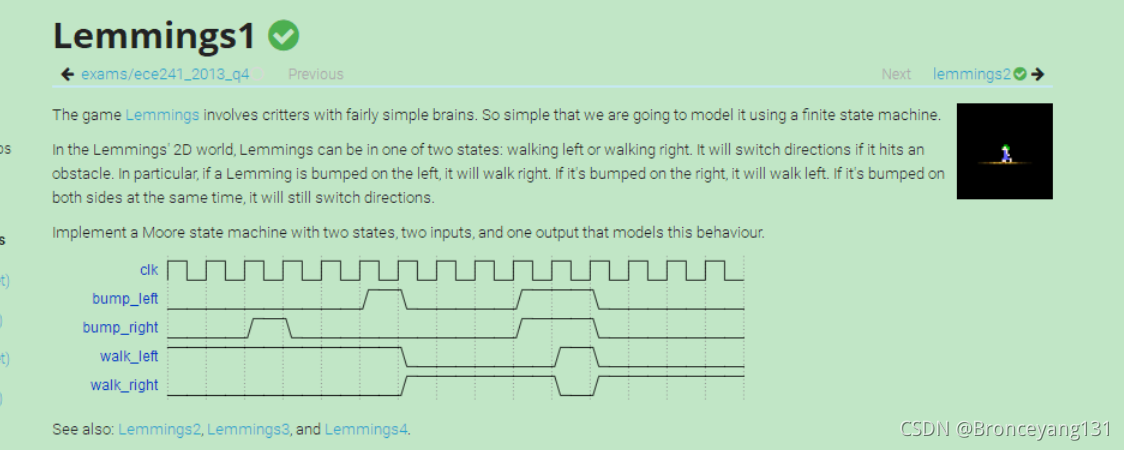
举个状态机的例子吧!!
问题如下:
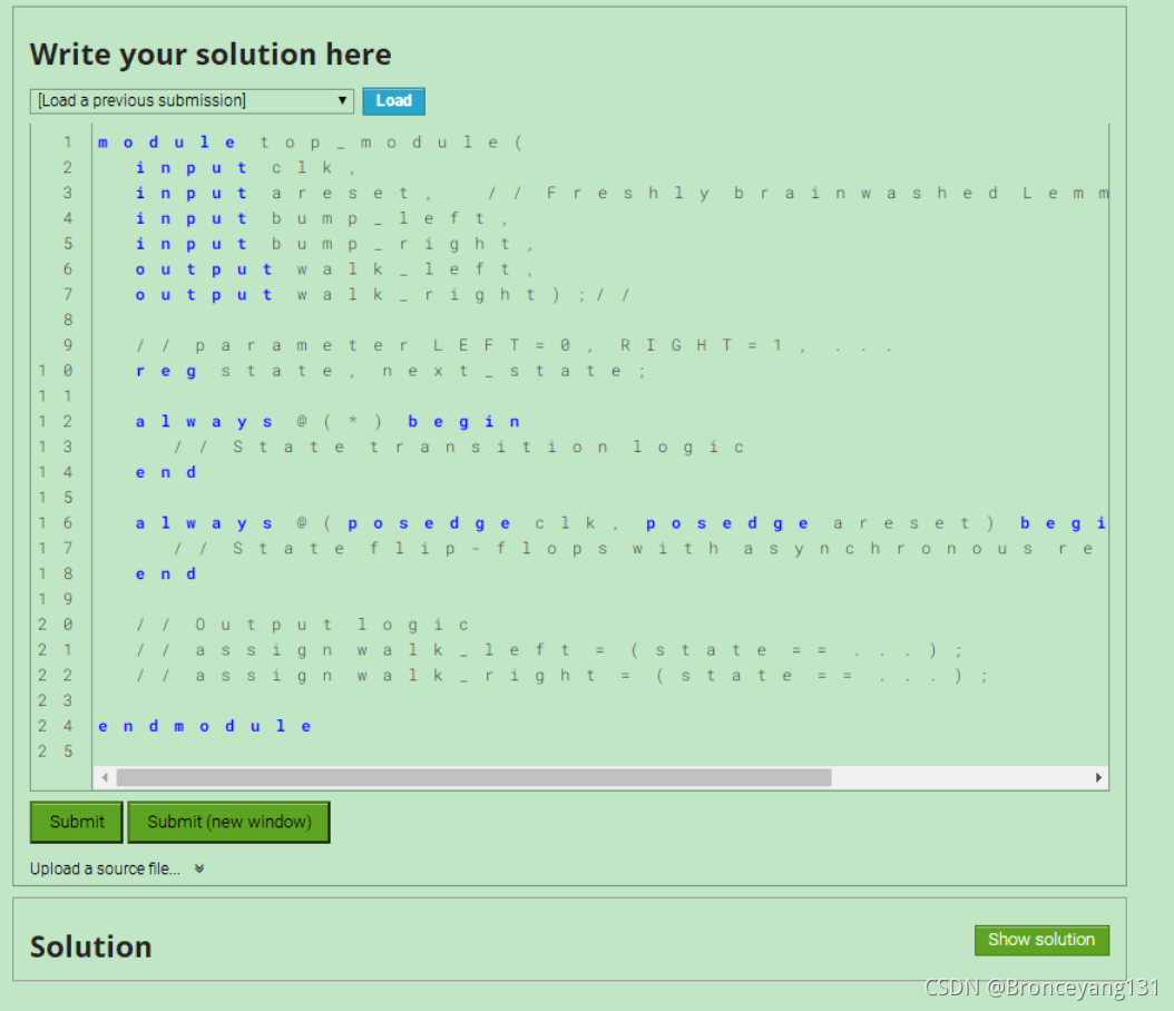
让你写程序,写完就可以提交综合仿真:
module top_module(
    input clk,
    input areset,    // Freshly brainwashed Lemmings walk left.
    input bump_left,
    input bump_right,
    output walk_left,
    output walk_right); //

    // parameter LEFT=0, RIGHT=1, ...
    parameter LEFT=0, RIGHT=1;
    reg state, next_state;

    always @(*) begin
        // State transition logic
        case(state)
            LEFT:begin
                case({bump_left,bump_right})
                    2'b00:next_state<=LEFT;
                    2'b01:next_state<=LEFT;
                    2'b10:next_state<=RIGHT;
                    2'b11:next_state=RIGHT;
                endcase
            end
            RIGHT:begin
                case({bump_left,bump_right})
                    2'b00:next_state<=RIGHT;
                    2'b01:next_state<=LEFT;
                    2'b10:next_state<=RIGHT;
                    2'b11:next_state=LEFT;
                endcase
            end
        endcase
    end

    always @(posedge clk, posedge areset) begin
        // State flip-flops with asynchronous reset
        if(areset)begin
            state<=LEFT;
        end
        else begin
            state<=next_state;
        end
    end

    // Output logic
     assign walk_left = (state == LEFT);
     assign walk_right = (state == RIGHT);

endmodule
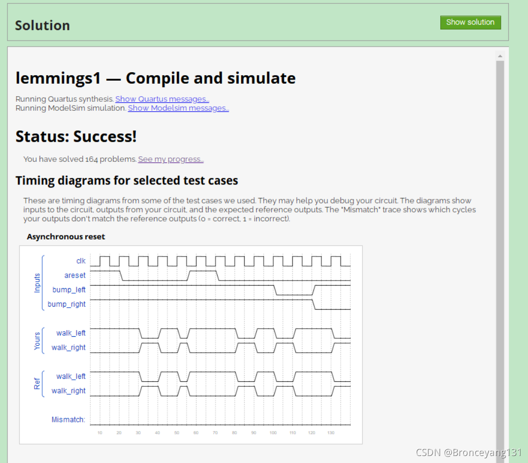
提交之后得到的仿真结果,错误会报错并提示错误信息。部分题也有编写程序的提示和提交正确后给出参考代码。
这个题的 官方参考代码:
module top_module (
	input clk,
	input areset,
	input bump_left,
	input bump_right,
	output walk_left,
	output walk_right
);

	// Give state names and assignments. I'm lazy, so I like to use decimal numbers.
	// It doesn't really matter what assignment is used, as long as they're unique.
	parameter WL=0, WR=1;
	reg state;
	reg next;


    // Combinational always block for state transition logic. Given the current state and inputs,
    // what should be next state be?
    // Combinational always block: Use blocking assignments.
    always@(*) begin
		case (state)
			WL: next = bump_left  ? WR : WL;
			WR: next = bump_right ? WL : WR;
		endcase
    end


    // Combinational always block for state transition logic. Given the current state and inputs,
    // what should be next state be?
    // Combinational always block: Use blocking assignments.
    always @(posedge clk, posedge areset) begin
		if (areset) state <= WL;
        else state <= next;
	end


	// Combinational output logic. In this problem, an assign statement are the simplest.
	// In more complex circuits, a combinational always block may be more suitable.
	assign walk_left = (state==WL);
	assign walk_right = (state==WR);


endmodule
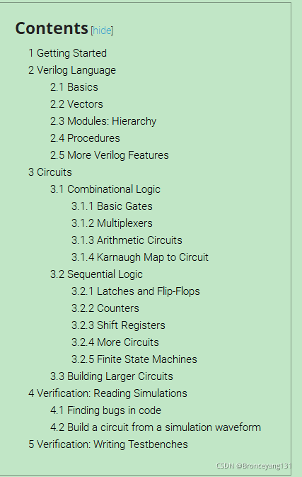
HDLBits网站题库主要分以下这几个主题,近期将简单总结分享一下。
这6个主题之下又可以分几个小节构成,每个小节针对一个知识内容进行针对性训练。如下图所示。
链接地址:
Problem sets
Contents
- 1 Getting Started
- 2 Verilog Language
- 3 Circuits
- 4 Verification: Reading Simulations
- 5 Verification: Writing Testbenches
Getting Started
Verilog Language
Basics
Vectors
- Vectors
- Vectors in more detail
- Vector part select
- Bitwise operators
- Four-input gates
- Vector concatenation operator
- Vector reversal 1
- Replication operator
- More replication
Modules: Hierarchy
- Modules
- Connecting ports by position
- Connecting ports by name
- Three modules
- Modules and vectors
- Adder 1
- Adder 2
- Carry-select adder
- Adder-subtractor
Procedures
Procedures include always, initial, task, and function blocks. Procedures allow sequential statements (which cannot be used outside of a procedure) to be used to describe the behaviour of a circuit.
- Always blocks (combinational)
- Always blocks (clocked)
- If statement
- If statement latches
- Case statement
- Priority encoder
- Priority encoder with casez
- Avoiding latches
More Verilog Features
- Conditional ternary operator
- Reduction operators
- Reduction: Even wider gates
- Combinational for-loop: Vector reversal 2
- Combinational for-loop: 255-bit population count
- Generate for-loop: 100-bit binary adder 2
- Generate for-loop: 100-digit BCD adder
Circuits
Combinational Logic
Basic Gates
- Wire
- GND
- NOR
- Another gate
- Two gates
- More logic gates
- 7420 chip
- Truth tables
- Two-bit equality
- Simple circuit A
- Simple circuit B
- Combine circuits A and B
- Ring or vibrate?
- Thermostat
- 3-bit population count
- Gates and vectors
- Even longer vectors
Multiplexers
- 2-to-1 multiplexer
- 2-to-1 bus multiplexer
- 9-to-1 multiplexer
- 256-to-1 multiplexer
- 256-to-1 4-bit multiplexer
Arithmetic Circuits
- Half adder
- Full adder
- 3-bit binary adder
- Adder
- Signed addition overflow
- 100-bit binary adder
- 4-digit BCD adder
Karnaugh Map to Circuit
- 3-variable
- 4-variable
- 4-variable
- 4-variable
- Minimum SOP and POS
- Karnaugh map
- Karnaugh map
- K-map implemented with a multiplexer
Sequential Logic
Latches and Flip-Flops
- D flip-flop
- D flip-flops
- DFF with reset
- DFF with reset value
- DFF with asynchronous reset
- DFF with byte enable
- D Latch
- DFF
- DFF
- DFF+gate
- Mux and DFF
- Mux and DFF
- DFFs and gates
- Create circuit from truth table
- Detect an edge
- Detect both edges
- Edge capture register
- Dual-edge triggered flip-flop
Counters
- Four-bit binary counter
- Decade counter
- Decade counter again
- Slow decade counter
- Counter 1-12
- Counter 1000
- 4-digit decimal counter
- 12-hour clock
Shift Registers
- 4-bit shift register
- Left/right rotator
- Left/right arithmetic shift by 1 or 8
- 5-bit LFSR
- 3-bit LFSR
- 32-bit LFSR
- Shift register
- Shift register
- 3-input LUT
More Circuits
- Cellular automata
Finite State Machines
- Simple FSM 1 (asynchronous reset)
- Simple FSM 1 (synchronous reset)
- Simple FSM 2 (asynchronous reset)
- Simple FSM 2 (synchronous reset)
- Simple state transitions 3
- Simple one-hot state transitions 3
- Simple FSM 3 (asynchronous reset)
- Simple FSM 3 (synchronous reset)
- Design a Moore FSM
- Lemmings 1
- Lemmings 2
- Lemmings 3
- Lemmings 4
- One-hot FSM
- PS/2 packet parser
- PS/2 packet parser and datapath
- Serial receiver
- Serial receiver and datapath
- Serial receiver with parity checking
- Sequence recognition
- Q8: Design a Mealy FSM
- Q5a: Serial two's complementer (Moore FSM)
- Q5b: Serial two's complementer (Mealy FSM)
- Q3a: FSM
- Q3b: FSM
- Q3c: FSM logic
- Q6b: FSM next-state logic
- Q6c: FSM one-hot next-state logic
- Q6: FSM
- Q2a: FSM
- Q2b: One-hot FSM equations
- Q2a: FSM
- Q2b: Another FSM
Building Larger Circuits
- 4-bit shift register and down counter
- FSM: Sequence 1101 recognizer
- FSM: Enable shift register
- FSM: The complete FSM
- The complete timer
- FSM: One-hot logic equations
Verification: Reading Simulations
Finding bugs in code
Build a circuit from a simulation waveform
- Combinational circuit 1
- Combinational circuit 2
- Combinational circuit 3
- Combinational circuit 4
- Combinational circuit 5
- Combinational circuit 6
- Sequential circuit 7
- Sequential circuit 8
- Sequential circuit 9
- Sequential circuit 10
