1 前言
写作动机:有客户先bootloader初始化GIC, 然后一个新的 image 重新初始化了 GIC 包括 ITS device,然后启动发现收不到中断。且 LPI enable bit 无法清零。
1.1 What is GIC?
GIC控制器将来自外设的中断分出优先级,然后分配给合适的core。 GIC是Arm Cortex-A 以及 Arm Cortex-R 的标准中断控制器。GIC提供灵活的可裁剪的方法进行中断管理,支持1个core到多个core的芯片设计。GIC有GICv3, GICv4等版本且在不断进化,往往ARM core版本越高,GIC也相应是高版本。
2 GIC 功能介绍
参考arm官网
2.1 GIC 中断分类
SPI, PPI, SGI 中断,和LPI中断。详情看这页arm官网。
2.2 提供两种中断信号发送到中断控制器的方式
- 硬件方式:每个外设通过一条专用的硬件信号线与中断控制器相连。
- 软件消息信号中断MSI方式:不需要硬件接线,外设通过向中断控制器的特定寄存器写入消息来发出中断请求(消息包含了中断的相关信息,如中断号、优先级等)。
对于共享外设中断(SPI),可以选择使用MSI或传统方式。
对于低功耗中断(LPI),总是使用MSI方式。
不同类型的中断使用不同的寄存器来传递消息。
2.3 中断状态机
SPI, PPI, SGI使用同一种状态机,包括四部分:
Inactive:中断源当前未被设置
Pending:中断被设置了,但中断源还没被PE通知。
Active:中断被设置了,但中断源被PE通知了。
Active and Pending:一个实例被通知了,另外一个处于pengding。
中断的生命周期取决于是否被配置为电平敏感或边沿触发的。
- 对电平敏感中断,中断的上升沿输入造成中断状态为pending,当外设取消中断信号后,中断才被设置。
- 对边沿敏感中断,一个中断的上升沿输入造成中断状态为pending, 但中断没有被设置。
LPI中断与他们不同,LPI只有两种状态:Inactive , Pending。
2.4 编程模型
GICv3中断控制器的寄存器接口被分为3组:
- Distributor
- Redistributor
- CPU
这三种接口,前俩 用于配置中断,后者用于处理中断。
简单介绍上面的接口:
-
Distributor:分配寄存器是内存映射的,用于配置SPI的。提供了一个编程接口用来:
SPI中断优先级和分配,
使能或失能SPI,
设置SPI优先级,
设置电平敏感还是边沿敏感,
控制SPI的pending状态还是active状态,
决定每个安全状态中使用的程序模型:affinity routing or legacy。 -
Redistributors
每个被连接的core都有一个Redistributor,Redistributors 提供了一个编程模型用来:
使能或失能SGIs 和 PPIs,
设置SGIs 和 PPIs的优先级,边沿敏感还是电平敏感
分配每个 SGI and PPI 到一个中断组
控制SGIs and PPI的状态
为memory中支持LPIs的中断属性和pending状态分配的数据结构体分配基地址。
为所有连接的PE提供电源管理支持 -
CPU interfaces
每个core包含处理器接口,这是在中断处理期间使用的中断寄存器。CPU接口提供编程接口。
提供通用控制和配置来使能中断处理。
确认中断
执行优先级下降和中断停用。
设置PE中断优先级掩码
定义PE抢占策略
确定 PE 的最高优先级挂起中断
在使用这些寄存器之前,软件必须启用系统寄存器接口。这由 ICC_SRE_ELn 寄存器中的 SRE 位控制,其中 n 指定异常级别:EL1-EL3。
3 GIC v3/v4 LPI 中断介绍
参考arm官网之LPI中断。
3.1 LPI简介(引出ITS,MSI)
这个文档为需要理解MSI是如何被GIC转换的、LPI是如何被管理的人以及需要在裸核条件下配置GIC的人设计的。
先引出几个概念:
LPI(Locality-specific Peripheral Interrupts)
MSIs(Message-Signaled Interrupts) 基于消息的中断,上一节讲了
ITS(Interrupt Translation Service)
一句话总结概括:LPI是一种MSI中断,ITS 负责将来自外设的消息翻译成LPI,然后转发到合适的 Redistributor 中,Redistributor将中断送给cpu interface处理并记录状态。
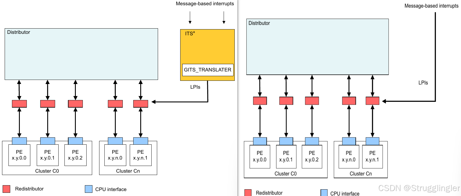
LPI 通常用于 MSIs 的外设。 LPI 的配置和管理不同于其他中断,因为他的状态存储在一段memory中而非寄存器中,LPI属于MSI。上图展示了两种 LPI 的触发方式,一种是直接发送 LPI INTID 到 Redistributors , 另一种是通过 ITS 将来自设备的 EventID 转化为 LPI INTID 后发送给 Redistributors。
然后文档从 Redistributors 和 ITS 如何配置展开介绍 LPI 中断的配置生成处理过程。其中延申除了一些名词,理解LPI中断就是理解这些名词之间的关系。之后才能理解代码。
3.2 Redistributors
开局一张图:
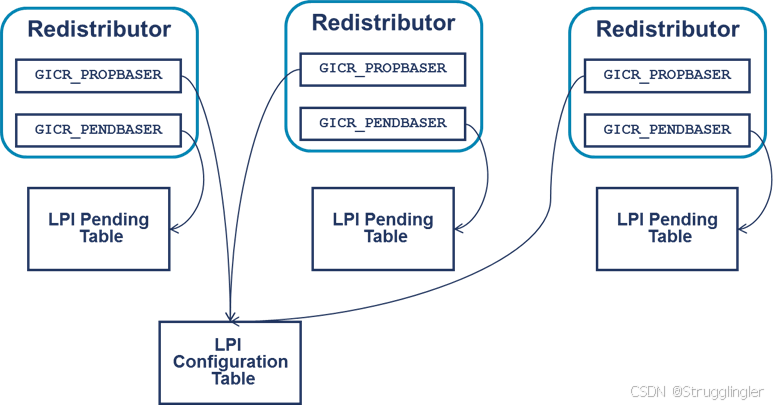
一句话总结概括:LPI 的配置信息和状态信息被存储在位于memory中的不同种类的 table 中,Redistributors 通过不同的寄存器来分别记录这些不同种类table的地址来监控以及配置LPI。
【插播一条,下面会提到很多寄存器,可能会蒙圈,先有个概念:】
GIC_v3中多了很多寄存器,对寄存器存在两种访问方式,一种是memory-mapped的方式(实现在GIC内部),一种是系统寄存器访问(在core内部实现)。
memory-mapped访问的寄存器:
GICC: cpu interface 寄存器
GICD: distributor 寄存器
GICH: virtual interface 控制寄存器,在hypervisor模式访问
GICR: redistributor 寄存器
GICV: virtual cpu interface 寄存器
GITS: ITS 寄存器,
系统寄存器访问的寄存器:
ICC: 物理 cpu interface 系统寄存器
ICV: 虚拟 cpu interface 系统寄存器
ICH: 虚拟 cpu interface 控制系统寄存器
概念展开:
-
LPI Configuration table 配置表:
每个 INTID 在配置表中占一个字节。GIC能读取这块内存,但不能写入。
LPI 配置表是全局的,一个系统就一个配置表被所有 Redistributors 共享。
Redistributors 的 GICR_PENDBASER 寄存器指向 LPI 配置表。
详情看官网。 -
LPI Pending table 状态表(字节起的名):
因为LPI中断只有两种状态(inactive or pending),所以每个 INTID 在 LPI 状态表中只占一位。
每个 Redistributors 有自己的 LPI Pending table,由 GICR_PENDBASER 指向。
中断控制器必须能够读取和写入为 LPI Pending table 分配的内存。
Redistributor 在需要缓存的待处理中断过多或进入低功耗状态时将状态信息写入 LPI Pending table。
软件绝不会直接访问 LPI Pending table(无法理解)。
GICR_PROPBASER.ID 位控制着 INTID 范围的大小,因此他影响着 LPI Configuration table 和 LPI Pending table 的大小。
理解了概念后,咱们看Redistributor如何初始化:
- 为 LPI Configuration table 分配内存,并使用每个 LPI 的适当配置初始化该表。
- 设置每个Redistributor 的 GICR_PROPBASER 指向 LPI Configuration table
- 为每个 Redistributor 申请 LPI Pending table 并初始化,系统启动时,意味着 zeroing the memory, 意味着 LPI INTIDs 处于 inactive state.
- 设置每个 Redistributor 的 GICR_PENDBASER 指向与自身关联的 LPI Pending table.
- 设置每个 Redistributor 的 GICR_CTLR.EnableLPIs 位为1.
LPI配置信息存储在 memory 中的一个table中,而非寄存器中,出于性能原因,Redistributors 会缓存LPI 配置信息。这意味着为了重新配置LPI,软件必须: - 更新LPI Configuration table中的entry
- 确保更新的全局可见性
- 使Redistributors中的任何缓存配置无效
3.3 ITS
一句话总结概括:ITS完成从message到可传输到连接的core的INTID的转换。
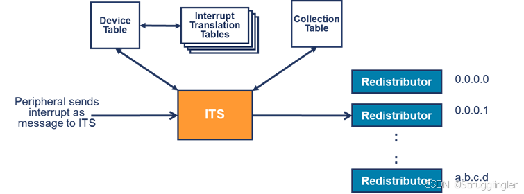
外围设备通过写入 message 到 ITS 中的 GITS_TRANSLATER 来生成 LPI, ITS 将 message 处理,配合 ITS 的一系列 table 将 message 其转化成可供 core 识别的 INTID。
概念展开:
table 包含 Device table,Interrupt Translation Tables(ITT),Collection table,然后他们之间的关系如下图所示:
图示来源
看图解释:
- 外设的 message 包含 EventID(标识外设正在发送哪个中断) 和 DeviceID(标识是哪个外设)。
- 在 Device table 中用 DeviceID 选择合适的entry。这个 entry 定义了使用哪个 ITT(每个DeviceID or peripheral一个)。
- 用 EventID 从所选 ITT 中选择适当的entry ,该 entry 提供了 INTID 和 Collection ID。
- 用 Collection ID 选择 Collection table 中的需要的entry, 返回路由信息。
- ITS 将中断转发到目标 Redistributor.
ITS 是由 ITS 的命令控制,ITS 命令存储在命令队列中, 命令队列是受ITS的三个寄存器控制的一段循环缓冲区:
- GITS_CBASER:寄存器定义了基地址和命令队列的大小,命令队列必须是64K对齐的,并且大小必须是4K的倍数。命令队列中的每个 entry 32 个字节。GITS_CBASER 还指定 ITS 在访问命令队列时使用的可缓存性和可共享性设置。
- GITS_CREADR:该寄存器指向 ITS 将处理的下一个命令。
- GITS_CWRITER:该寄存器指向队列中应写入下一个新命令的条目。
【注】:Arm Generic Interrupt Controller Architecture Specification GIC architecture version 3.0 and 4.0 中提供了所有ITS支持的命令细节已经如何编码。
然后文档后续讲解了 ITS 的初始化配置流程,如何申请Collection and Device tables,向命令队列添加命令。
ARM GICv3 GIC代码分析
先看看设备树:
	gic: interrupt-controller@6000000 {
		compatible = "arm,gic-v3";
		reg = <0x0 0x06000000 0 0x10000>, // GIC Dist (GICD)
			<0x0 0x06200000 0 0x200000>,  // GICR (RD_base +  SGI_base)
			<0x0 0x0c0c0000 0 0x2000>,    // GICC
			<0x0 0x0c0d0000 0 0x1000>,    // GICH
			<0x0 0x0c0e0000 0 0x20000>;   // GICV
		#interrupt-cells = <3>;
		#address-cells = <2>;
		#size-cells = <2>;
		ranges;
		interrupt-controller;
		interrupts = <GIC_PPI 9 IRQ_TYPE_LEVEL_HIGH>;

		its: gic-its@6020000 {
			compatible = "arm,gic-v3-its";
			msi-controller;
			reg = <0x0 0x6020000 0 0x20000>;
		};
	};
然后看代码:
static int __init gic_of_init(struct device_node *node, struct device_node *parent)
{
		/* map设备树中第 0 个mmio内存,也就是GICD */
        dist_base = of_iomap(node, 0);
		/* 获取GIC版本号:dist_base + GICD_PIDR2(0xFFE8) */
        err = gic_validate_dist_version(dist_base);

		/* 获取有多少个distributor,我们dts没设置,默认1个,所以在这被置1 */
        if (of_property_read_u32(node, "#redistributor-regions", &nr_redist_regions))
                nr_redist_regions = 1;
        rdist_regs = kcalloc(nr_redist_regions, sizeof(*rdist_regs),
                             GFP_KERNEL);

		/*  */
        for (i = 0; i < nr_redist_regions; i++) {
                struct resource res;
                int ret;
				/* 获取设备树中 reg 中第i+1个地址范围 */
                ret = of_address_to_resource(node, 1 + i, &res);
				/* map设备树中第 i+1 个mmio内存,依次为 GICR GICC GICH GICV */
                rdist_regs[i].redist_base = of_iomap(node, 1 + i);

                rdist_regs[i].phys_base = res.start;
        }
		/* 获取redistributor的宽度,我这个好像没 */
        if (of_property_read_u64(node, "redistributor-stride", &redist_stride))
                redist_stride = 0;

		...

        err = gic_init_bases(dist_base, rdist_regs, nr_redist_regions,
                             redist_stride, &node->fwnode);
		...
}
static int __init gic_init_bases(void __iomem *dist_base,
                                 struct redist_region *rdist_regs,
                                 u32 nr_redist_regions,
                                 u64 redist_stride,
                                 struct fwnode_handle *handle)
{
		...

        /* 从 GICD_TYPER 获取支持的最大中断号是多少 */
        typer = readl_relaxed(gic_data.dist_base + GICD_TYPER);

		...

        irq_domain_update_bus_token(gic_data.domain, DOMAIN_BUS_WIRED);

        gic_data.has_rss = !!(typer & GICD_TYPER_RSS);
        pr_info("Distributor has %sRange Selector support\n",
                gic_data.has_rss ? "" : "no ");
        if (typer & GICD_TYPER_MBIS) {
                err = mbi_init(handle, gic_data.domain);
                if (err)
                        pr_err("Failed to initialize MBIs\n");
        }

		/* 注册中断上半部回调函数 */
        set_handle_irq(gic_handle_irq);

		...
		/* 初始化各个寄存器 */
        gic_dist_init();
        gic_cpu_init(); // 初始化CPU interface.
        gic_smp_init();
		/* 电源管理相关,不展开 */
        gic_cpu_pm_init();

        if (gic_dist_supports_lpis()) {
				/* 如果支持 ITS ,初始化LPI/ITS */
                its_init(handle, &gic_data.rdists, gic_data.domain);
                its_cpu_init();
        } else {
                if (IS_ENABLED(CONFIG_ARM_GIC_V2M))
                        gicv2m_init(handle, gic_data.domain);
        }

        gic_enable_nmi_support();
		...
}
static void __init gic_dist_init(void)
{
        unsigned int i;
#ifndef CONFIG_GIC_GENTLE_CONFIG
        u64 affinity;
#endif
        void __iomem *base = gic_data.dist_base;
        u32 val;

#ifdef CONFIG_GIC_GENTLE_CONFIG
       /* 在运行多个操作系统的 SoC 中,这些操作系统在 ARM 集群上共享同一个 GIC,当另一个操作系统已经配置了 distributor 时,我们会注意不要重新配置 distributor,否则可能会干扰 */
       u32 gicd_ctlr = readl_relaxed(base + GICD_CTLR);
#endif
        /* 禁用 distributor */
        writel_relaxed(0, base + GICD_CTLR);
		/* 通过监控GICD_CTLR特定位等待禁用操作完成 */
        gic_dist_wait_for_rwp();

        /*
         * Configure SPIs as non-secure Group-1. This will only matter
         * if the GIC only has a single security state. This will not
         * do the right thing if the kernel is running in secure mode,
         * but that's not the intended use case anyway.
         */
        for (i = 32; i < GIC_LINE_NR; i += 32)
                writel_relaxed(~0, base + GICD_IGROUPR + i / 8);

        /* Extended SPI range, not handled by the GICv2/GICv3 common code */
        for (i = 0; i < GIC_ESPI_NR; i += 32) {
                writel_relaxed(~0U, base + GICD_ICENABLERnE + i / 8);
                writel_relaxed(~0U, base + GICD_ICACTIVERnE + i / 8);
        }

        for (i = 0; i < GIC_ESPI_NR; i += 32)
                writel_relaxed(~0U, base + GICD_IGROUPRnE + i / 8);

        for (i = 0; i < GIC_ESPI_NR; i += 16)
                writel_relaxed(0, base + GICD_ICFGRnE + i / 4);
        for (i = 0; i < GIC_ESPI_NR; i += 4)
                writel_relaxed(GICD_INT_DEF_PRI_X4, base + GICD_IPRIORITYRnE + i);

        /* Now do the common stuff, and wait for the distributor to drain */
        gic_dist_config(base, GIC_LINE_NR, gic_dist_wait_for_rwp);

        val = GICD_CTLR_ARE_NS | GICD_CTLR_ENABLE_G1A | GICD_CTLR_ENABLE_G1;
        if (gic_data.rdists.gicd_typer2 & GICD_TYPER2_nASSGIcap) {
                pr_info("Enabling SGIs without active state\n");
                val |= GICD_CTLR_nASSGIreq;
        }

        /* 使能 distributor */
        writel_relaxed(val, base + GICD_CTLR);

#ifndef CONFIG_GIC_GENTLE_CONFIG
        /* In a SoC running multiple OSes on ARM clusters sharing the same GIC,
         * do not set the affinity to all interrupts as this
         * would conflict with the other cluster's GIC configuration.
         * This is now done in function gic_set_type() (called by request_irq)
         * which allows to limit this to the interrupts registered by the
         * cluster.
         */
        /*
         * Set all global interrupts to the boot CPU only. ARE must be
         * enabled.
         */
		/* 初始化中断亲和性,全部绑定中断到当前cpu */
        affinity = gic_mpidr_to_affinity(cpu_logical_map(smp_processor_id()));
        for (i = 32; i < GIC_LINE_NR; i++)
                gic_write_irouter(affinity, base + GICD_IROUTER + i * 8);

        for (i = 0; i < GIC_ESPI_NR; i++)
                gic_write_irouter(affinity, base + GICD_IROUTERnE + i * 8);
#endif
}
static void gic_cpu_init(void)
{
        /* 填充 redistributor 结构体基地址 */
        if (gic_populate_rdist())
                return;
		/* 使能redistributor 就是写GICR_WAKER,然后忙等结果 */
        gic_enable_redist(true);
		...
		/* 清除PPI\SGI中断设置默认中断优先级 */
		gic_cpu_config(rbase, gic_data.ppi_nr + 16, gic_redist_wait_for_rwp);
		/* 初始化系统寄存器 */
		gic_cpu_sys_reg_init();
}
static int gic_populate_rdist(void)
{
        pr_info("%s(): GICTT CPU-%d will call gic_iterate_rdists\n", __func__, smp_processor_id());
        if (gic_iterate_rdists(__gic_populate_rdist) == 0)
                return 0;
		...
}
/* 填充redistributor */
static int __gic_populate_rdist(struct redist_region *region, void __iomem *ptr)
{
        unsigned long mpidr = cpu_logical_map(smp_processor_id());
        u64 typer;
        u32 aff;

		/*
		 * 生成以一个当前核心的中断亲和值
		 * #define MPIDR_AFFINITY_LEVEL(mpidr, level) ((mpidr >> (8 * level)) & 0b11111111)
		 */
        aff = (MPIDR_AFFINITY_LEVEL(mpidr, 3) << 24 |
               MPIDR_AFFINITY_LEVEL(mpidr, 2) << 16 |
               MPIDR_AFFINITY_LEVEL(mpidr, 1) << 8 |
               MPIDR_AFFINITY_LEVEL(mpidr, 0));
		/* 读取 GICR_TYPER,存储 Redistributor 的配置信息 */
        typer = gic_read_typer(ptr + GICR_TYPER);
		/* 如果 Redistributor 绑定的就是当前核心 */
        if ((typer >> 32) == aff) {
				/* 填充结构体基地址 */
                u64 offset = ptr - region->redist_base;
                raw_spin_lock_init(&gic_data_rdist()->rd_lock);
                gic_data_rdist_rd_base() = ptr;
                gic_data_rdist()->phys_base = region->phys_base + offset;
                pr_info("CPU%d: GICTT found redistributor %lx region %d:%pa phy:0x%llX offset:0x%llX\n",
                        smp_processor_id(), mpidr,
                        (int)(region - gic_data.redist_regions),
                        &gic_data_rdist()->phys_base, gic_data_rdist()->phys_base, offset);
                return 0;
        }

        /* Try next one */
        return 1;
}
/***********************************************************************/
static void __init gic_smp_init(void)
{
        struct irq_fwspec sgi_fwspec = {
                .fwnode         = gic_data.fwnode,
                .param_count    = 1,
        };
        int base_sgi;

        cpuhp_setup_state_nocalls(CPUHP_AP_IRQ_GIC_STARTING,
                                  "irqchip/arm/gicv3:starting",
                                  gic_starting_cpu, NULL);

        /* Register all 16 non-secure SGIs */
        base_sgi = __irq_domain_alloc_irqs(gic_data.domain, -1, 16,
                                           NUMA_NO_NODE, &sgi_fwspec,
                                           false, NULL);
        if (WARN_ON(base_sgi <= 0))
                return;

        set_smp_ipi_range(base_sgi, 16);
}
ITS通过命令队列来配置前面提到的三个 table ,分别是
CBASER:指向一个内存空间,代表命令存放的环形队列,命令就放入这个环形队列中
CREADR:指示GIC目前读取环形队列的位置,读取GIC处理了多少数据
CWRITER:指示当前环形缓冲区写入位置,告诉GIC写入数据了
下面我们开始看代码:
我们从 gic_init_bases 开始看,在 gic_init_bases 的结尾初始化ITS,分别调用了 its_init 和 its_cpu_init 两个关键函数:
gic_of_init
|
|-> gic_init_bases
	|-->gic_cpu_init() //初始化CPU interface.
	|	|-->gic_populate_rdist()
	|
	|
	|-->its_init()
		|-->its_of_probe()初始化 its node 数据结构, 为 its tables 分配内存, 初始化its domain并注册its domain相关操作。
			|
			|->its_probe_one()三个入口参数
				|
				|-->alloc_pages_node // 为 命令队列 申请内存
				|-->its_alloc_tables // 分配设备表???
						its_setup_baser
							alloc_pages_node
				|-->its_init_domain //猜测:初始化its domain并注册its domain相关操作。 并创建基数树
				在its_init_domain中的info->ops得到了如下ops接口
					|--	its_msi_prepare
						|
						|-->its_find_device 根据dev_id查找entry. 返回值为its_device类型结构体,其实就是device. 但是返回值为空的。没找到。
						|
						|-->its_create_device
							|
							|-->its_alloc_device_table // 申请 device_table
							|-->its_lpi_alloc 申请内核空间存放 lpi中断。
							|-->its_send_mapd //Map device to its ITT
								|-->its_send_single_command(dev->its, its_build_mapd_cmd, &desc); //填充 Device Table
		|
		|
		|-->allocate_lpi_tables() 初始化LPI需要的两张表(LPI configuration table, LPI pending tables(每个Redistributor一个))
		|
		|-->register_syscore_ops()注册两个低功耗流程会用到的函数
	|
	|->its_cpu_init //进行its的一些额外的配置,如 enable lpi 以及绑定 its collection 到 its 目的 redistributour。
		|--> its_cpu_init_lpis // 配置 GICR (redistributor寄存器)寄存器,GICR_PROPBASER 指向 LPI Configuration table, GICR_PENDBASER 指向与自身关联的 LPI Pending table. 以及使能lpi,函数第一行rbase得到的就是位于percpu区域的GICR(redistributor寄存器)基地址。
		|
		|--> its_cpu_init_collections // 绑定每一个 collection 到 target redistributor
			|
			|--> its_send_mapc // 发送its mapc command, mapc 主要用于映射 collection 到目的 redistributor
					|-->its_send_single_command(its, its_build_mapc_cmd, &desc); //填充 Collection Table
			|--> its_send_invall //指定 memory中的LPI中断的配置信息和cache中保存的必须一致
					|-->its_send_single_command(its, its_build_invall_cmd, &desc); //指定ITS必须保证由ICID定义的中断collection的任何缓存与所有Redistributor内存中LPI配置表保持一致
ITS使用命令来填他的三个转换表,基本的ITS命令去看 《IHI0069H_b_gic_architecture_specification.pdf 5.3》 章节。
最主要的命令有下面三个:
MAPD : 填充 Device Table(将DeviceID相关的设备表项映射到由ITT_addr和Size定义的ITT)
MAPI、MAPTI: 填充 Interrupt Traslation Table表(ITT)
MAPC : 填充 Collection Table(将ICID定义的collection表映射到RDbase定义的Redistributor)
ITS表的配置原理
上面出现了三次 its_send_single_command 应该是发送命令,下面来看一下代码里面是怎么组织命令和发送命令的,结合 MAPD 命令来一窥命令的发送过程:
// drivers/irqchip/.irq-gic-v3-its.c
/* Warning, macro hell follows */
#define BUILD_SINGLE_CMD_FUNC(name, buildtype, synctype, buildfn)       \
void name(struct its_node *its,                                         \
          buildtype builder,                                            \
          struct its_cmd_desc *desc)                                    \
{                                                                       \
        struct its_cmd_block *cmd, *sync_cmd, *next_cmd;                \
        synctype *sync_obj;                                             \
        unsigned long flags;                                            \
        u64 rd_idx;                                                     \
                                                                        \
        raw_spin_lock_irqsave(&its->lock, flags);                       \
                                                                        \
        cmd = its_allocate_entry(its);                                  \
        if (!cmd) {             /* We're soooooo screewed... */         \
                raw_spin_unlock_irqrestore(&its->lock, flags);          \
                return;                                                 \
        }                                                               \
        sync_obj = builder(its, cmd, desc);                             \
		/* 把cache中的数据刷到内存 */
        its_flush_cmd(its, cmd);                                        \
                                                                        \
        if (sync_obj) {                                                 \
		如果上面的builder需要做sync操作会返回值,然后根据宏定义代码块组织发送sync命令
                sync_cmd = its_allocate_entry(its);                     \
                if (!sync_cmd)                                          \
                        goto post;                                      \
                                                                        \
                buildfn(its, sync_cmd, sync_obj);                       \
				/* 把cache中的数据刷到内存 */
                its_flush_cmd(its, sync_cmd);                           \
        }                                                               \
                                                                        \
post:                                                                   \
		/* 前面说了让记住仨 ITS 寄存器。 记住没? 这就用上了 */
		/* 读 CREADR 寄存器的值,GIC目前读取环形队列的位置 */
        rd_idx = readl_relaxed(its->base + GITS_CREADR);                \
		/* 更新 CWRITER 寄存器的值,告诉GIC有命令写入 */
        next_cmd = its_post_commands(its);                              \
        raw_spin_unlock_irqrestore(&its->lock, flags);                  \
                                                                        \
		/* 读 CREADR 寄存器的值,等待处理完成 */
        if (its_wait_for_range_completion(its, rd_idx, next_cmd))       \
                pr_err_ratelimited("ITS cmd %ps failed\n", builder);    \
}
static struct its_cmd_block *its_allocate_entry(struct its_node *its)
{
        struct its_cmd_block *cmd;
        u32 count = 1000000;    /* 1s! */

        while (its_queue_full(its)) {
			// 队列满了
                count--;
                if (!count) {
                        pr_err_ratelimited("ITS queue not draining\n");
                        return NULL;
                }
                cpu_relax();
                udelay(1); // 盲等,延迟 1 微秒
        }
		// 队列没满
		/* 使用下一个空 command */
        cmd = its->cmd_write++;

        /* Handle queue wrapping */
        if (its->cmd_write == (its->cmd_base + ITS_CMD_QUEUE_NR_ENTRIES))
                its->cmd_write = its->cmd_base;

        /* Clear command  */
        cmd->raw_cmd[0] = 0;
        cmd->raw_cmd[1] = 0;
        cmd->raw_cmd[2] = 0;
        cmd->raw_cmd[3] = 0;

        return cmd;
}
static BUILD_SINGLE_CMD_FUNC(its_send_single_command, its_cmd_builder_t,
                             struct its_collection, its_build_sync_cmd)
上面这段代码是定义一个 its_send_single_command 函数,该函数在 its_send_mapc 等函数被调用,its_cmd_builder_t 为回调, its_build_sync_cmd 为同步命令,需要时使用。【其实这个宏相关函数的理解是关键】
static void its_send_mapc(struct its_node *its, struct its_collection *col,
                          int valid)
{
        struct its_cmd_desc desc;

        desc.its_mapc_cmd.col = col;
        desc.its_mapc_cmd.valid = !!valid;

        its_send_single_command(its, its_build_mapc_cmd, &desc);
}
回调如下函数:
static struct its_collection *its_build_mapc_cmd(struct its_node *its,
                                                 struct its_cmd_block *cmd,
                                                 struct its_cmd_desc *desc)
{
        its_encode_cmd(cmd, GITS_CMD_MAPC);
        its_encode_collection(cmd, desc->its_mapc_cmd.col->col_id);
        its_encode_target(cmd, desc->its_mapc_cmd.col->target_address);
        its_encode_valid(cmd, desc->its_mapc_cmd.valid);

        its_fixup_cmd(cmd);

        return desc->its_mapc_cmd.col;
}
总结: 观察ITS队列有空闲位置就往空闲位置里面写入数据,数据写入之后将cache刷出内存,如果要等待ITS响应命令就用sync命令去等待ITS操作。
参考
参考:https://blog.csdn.net/yhb1047818384/article/details/87561438
参考:https://blog.csdn.net/yhb1047818384/article/details/89061672
主要参考:https://blog.csdn.net/qq_16054639/article/details/142334293
挖坑1: arm64中断处理流程。
挖坑2: Linux irq_domain 相关介绍,可参考,无意间发现kernel 竟然有翻译介绍文档:./Documentation/translations/zh_CN/core-api/irq/irq-domain.rst 。