ADC数模转换
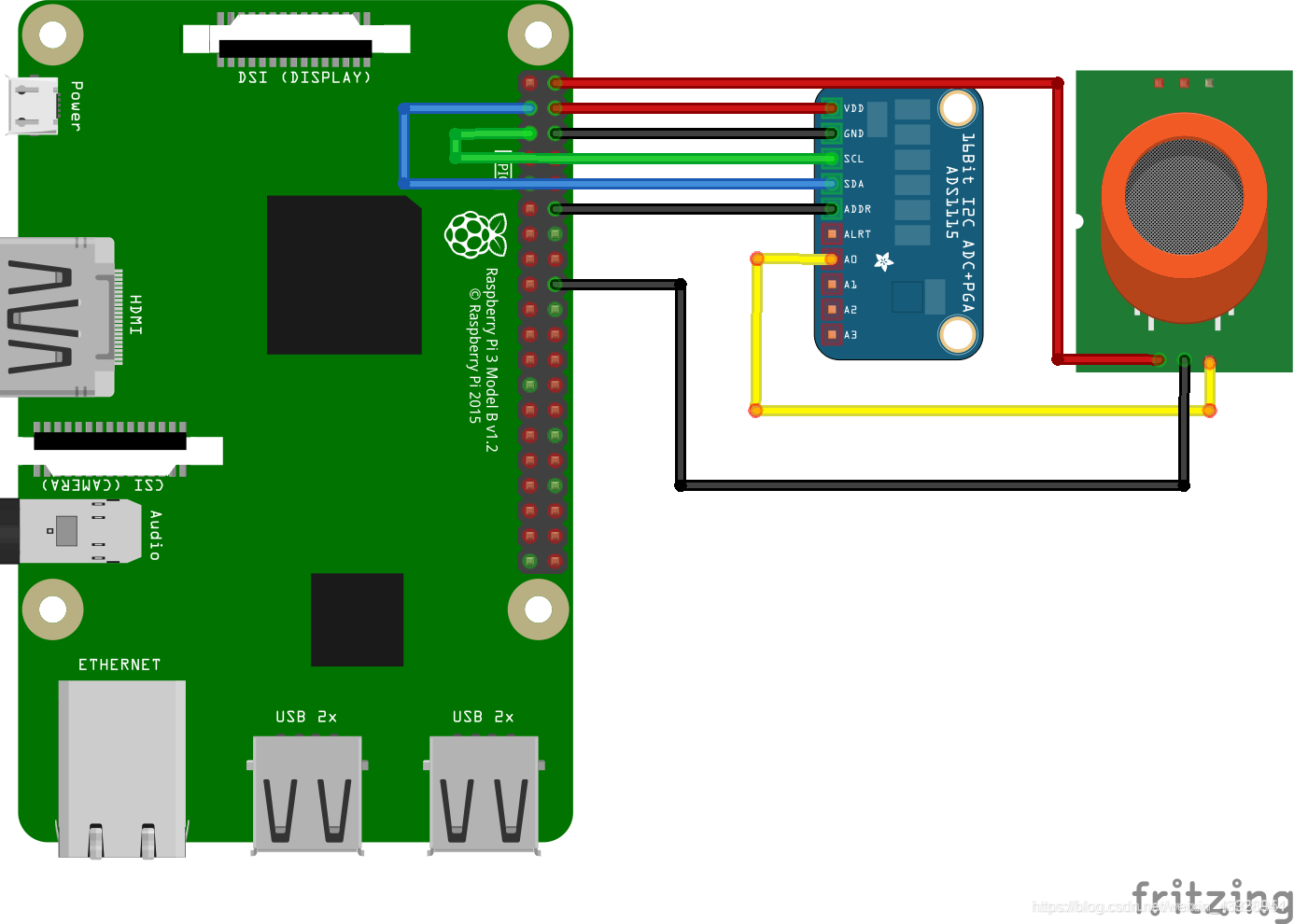
接线
VDD - 5V
GND - GND
SCL - SCL
SDA - SDA
ADDR - GND
A0 - MQ 传感器的 A0
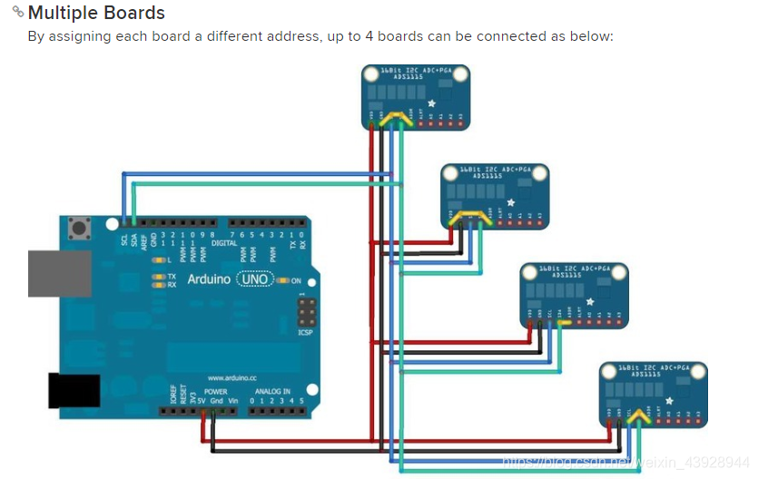
当ADDR引脚连接到GND时,地址为:0x48(0100, 1000B)
当ADDR引脚连接到VDD时,地址为:0x49(0100, 1001B)
当ADDR引脚连接到SDA时,地址为:0x4A(0100, 1010B)
当ADDR引脚连接到SCL时,地址为:0x4B(0100, 1011B)
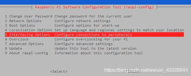
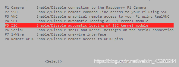
设置树莓(开启I2C)
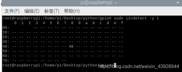
模块检查(接通电源后)
sudo apt-get install i2c-tools
sudo i2cdetect -y 1
安装依赖
pip3 install -i https://pypi.mirrors.ustc.edu.cn/simple/ Adafruit_ADS1x15
代码
import Adafruit_ADS1x15
/**
增益
2/3 = +/-6.144V
1 = +/-4.096V
2 = +/-2.048V
4 = +/-1.024V
8 = +/-0.512V
16 = +/-0.256V
*/
GAIN = 1
adc1 = Adafruit_ADS1x15.ADS1115(address=0x48)
while True:
	/**
		A0 = Channel 0 minus channel 1
    	A1 = Channel 0 minus channel 3
    	A2 = Channel 1 minus channel 3
    	A3 = Channel 2 minus channel 3
    	data_rate=128 为每秒返回样本数 最高为860
	*/
	print(adc1.read_adc(0, gain=GAIN, data_rate=128))
# Simple demo of reading each analog input from the ADS1x15 and printing it to
# the screen.
# Author: Tony DiCola
# License: Public Domain
import time

# Import the ADS1x15 module.
import Adafruit_ADS1x15


# Create an ADS1115 ADC (16-bit) instance.
adc = Adafruit_ADS1x15.ADS1115()

# Or create an ADS1015 ADC (12-bit) instance.
#adc = Adafruit_ADS1x15.ADS1015()

# Note you can change the I2C address from its default (0x48), and/or the I2C
# bus by passing in these optional parameters:
#adc = Adafruit_ADS1x15.ADS1015(address=0x49, busnum=1)

# Choose a gain of 1 for reading voltages from 0 to 4.09V.
# Or pick a different gain to change the range of voltages that are read:
#  - 2/3 = +/-6.144V
#  -   1 = +/-4.096V
#  -   2 = +/-2.048V
#  -   4 = +/-1.024V
#  -   8 = +/-0.512V
#  -  16 = +/-0.256V
# See table 3 in the ADS1015/ADS1115 datasheet for more info on gain.
GAIN = 1

print('Reading ADS1x15 values, press Ctrl-C to quit...')
# Print nice channel column headers.
print('| {0:>6} | {1:>6} | {2:>6} | {3:>6} |'.format(*range(4)))
print('-' * 37)
# Main loop.
while True:
    # Read all the ADC channel values in a list.
    values = [0]*4
    for i in range(4):
        # Read the specified ADC channel using the previously set gain value.
        values[i] = adc.read_adc(i, gain=GAIN)
        # Note you can also pass in an optional data_rate parameter that controls
        # the ADC conversion time (in samples/second). Each chip has a different
        # set of allowed data rate values, see datasheet Table 9 config register
        # DR bit values.
        #values[i] = adc.read_adc(i, gain=GAIN, data_rate=128)
        # Each value will be a 12 or 16 bit signed integer value depending on the
        # ADC (ADS1015 = 12-bit, ADS1115 = 16-bit).
    # Print the ADC values.
    print('| {0:>6} | {1:>6} | {2:>6} | {3:>6} |'.format(*values))
    # Pause for half a second.
    time.sleep(0.5)
