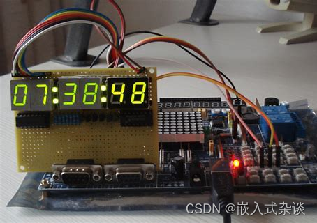
DS1302是一款低功耗的实时时钟芯片,被广泛应用于各种电子产品中。它具有准确计时、多种时间格式表示、定时报警等功能,适用于记录时间、日期和闹钟。在本文中,我们将介绍如何在基于STM32的开发环境中使用DS1302实时时钟模块,并给出一个完整的示例代码。
硬件连接:
首先,我们需要准备以下硬件:
- STM32单片机开发板
- DS1302实时时钟模块
连接方法如下:
- 将DS1302的SCK引脚连接到STM32的SCK引脚
- 将DS1302的SDA引脚连接到STM32的SDA引脚
- 将DS1302的RST引脚连接到STM32的RST引脚
- 将DS1302的VCC引脚连接到STM32的VCC引脚(一般为3.3V)
- 将DS1302的GND引脚连接到STM32的GND引脚
软件实现:
以下是一个基于STM32的DS1302实时时钟模块应用的示例代码:
```c
#include "stm32f10x.h"
#include "ds1302.h"

int main(void)
{
    // 初始化DS1302模块
    DS1302_Init();

    while (1)
    {
        // 读取实时时钟的时间
        uint8_t hour, minute, second;
        DS1302_GetTime(&hour, &minute, &second);

        // 读取实时时钟的日期
        uint8_t year, month, day;
        DS1302_GetDate(&year, &month, &day);

        // 在串口输出时间和日期
        printf("Current time: %02d:%02d:%02d\r\n", hour, minute, second);
        printf("Current date: %02d-%02d-%02d\r\n", year, month, day);

        // 延时一段时间
        delay_ms(1000);
    }
}
```
以上是一个简单的应用示例,该示例通过DS1302模块获取当前的时间和日期,并通过串口输出。在实际应用中,可以根据需要添加其他功能,如定时报警、时间设置等。
需要注意的是,在使用该示例代码之前,你需要提前编写一个适配器库`ds1302.h`和`ds1302.c`,用于实现DS1302模块的初始化、读写时间和日期等操作。你可以根据DS1302的数据手册编写适配器库,或者找到第三方提供的库。
接下来,我们将详细介绍如何编写`ds1302.h`和`ds1302.c`,以及其中的各个函数的实现。在这份代码中,我们假设使用的是STM32的标准外设库进行开发。
ds1302.h:

```c
#ifndef DS1302_H
#define DS1302_H

#include <stdint.h>

void DS1302_Init(void);
void DS1302_GetTime(uint8_t *hour, uint8_t *minute, uint8_t *second);
void DS1302_GetDate(uint8_t *year, uint8_t *month, uint8_t *day);
void DS1302_SetTime(uint8_t hour, uint8_t minute, uint8_t second);
void DS1302_SetDate(uint8_t year, uint8_t month, uint8_t day);

#endif
```

ds1302.c:

```c
#include "ds1302.h"
#include "stm32f10x.h"

// DS1302模块引脚定义
#define DS1302_RST_PIN GPIO_Pin_0
#define DS1302_SCK_PIN GPIO_Pin_1
#define DS1302_IO_PIN GPIO_Pin_2
#define DS1302_PORT GPIOB

// DS1302模块相关函数
void DS1302_WriteByte(uint8_t dat)
{
    uint8_t i;
    for (i = 0; i < 8; i++)
    {
        GPIO_ResetBits(DS1302_PORT, DS1302_SCK_PIN);
        if (dat & 0x01)
            GPIO_SetBits(DS1302_PORT, DS1302_IO_PIN);
        else
            GPIO_ResetBits(DS1302_PORT, DS1302_IO_PIN);
        GPIO_SetBits(DS1302_PORT, DS1302_SCK_PIN);
        dat >>= 1;
    }
}

uint8_t DS1302_ReadByte(void)
{
    uint8_t i, dat = 0;
    GPIO_InitTypeDef GPIO_InitStructure;
    GPIO_InitStructure.GPIO_Pin = DS1302_IO_PIN;
    GPIO_InitStructure.GPIO_Mode = GPIO_Mode_IPD;
    GPIO_Init(DS1302_PORT, &GPIO_InitStructure);

    for (i = 0; i < 8; i++)
    {
        dat >>= 1;
        GPIO_ResetBits(DS1302_PORT, DS1302_SCK_PIN);
        if (GPIO_ReadInputDataBit(DS1302_PORT, DS1302_IO_PIN))
            dat |= 0x80;
        GPIO_SetBits(DS1302_PORT, DS1302_SCK_PIN);
    }

    return dat;
}

void DS1302_Write(uint8_t reg, uint8_t dat)
{
    GPIO_ResetBits(DS1302_PORT, DS1302_RST_PIN);
    DS1302_WriteByte(reg);
    DS1302_WriteByte(dat);
    GPIO_SetBits(DS1302_PORT, DS1302_RST_PIN);
}

uint8_t DS1302_Read(uint8_t reg)
{
    uint8_t dat;
    GPIO_ResetBits(DS1302_PORT, DS1302_RST_PIN);
    DS1302_WriteByte(reg | 0x81);
    dat = DS1302_ReadByte();
    GPIO_SetBits(DS1302_PORT, DS1302_RST_PIN);

    return dat;
}

void DS1302_Init(void)
{
    GPIO_InitTypeDef GPIO_InitStructure;
    RCC_APB2PeriphClockCmd(RCC_APB2Periph_GPIOB, ENABLE);

    GPIO_InitStructure.GPIO_Pin = DS1302_RST_PIN | DS1302_SCK_PIN;
    GPIO_InitStructure.GPIO_Speed = GPIO_Speed_50MHz;
    GPIO_InitStructure.GPIO_Mode = GPIO_Mode_Out_PP;
    GPIO_Init(DS1302_PORT, &GPIO_InitStructure);

    GPIO_InitStructure.GPIO_Pin = DS1302_IO_PIN;
    GPIO_InitStructure.GPIO_Mode = GPIO_Mode_Out_OD;
    GPIO_Init(DS1302_PORT, &GPIO_InitStructure);

    DS1302_Write(0x8e, 0x00);  // 写入禁止写保护命令
}

void DS1302_GetTime(uint8_t *hour, uint8_t *minute, uint8_t *second)
{
    uint8_t data[3];
    for (int i = 0; i < 3; i++)
    {
        data[i] = DS1302_Read(0x81 + i * 2);  // 从RAM中读取时间数据
        if (i == 0)
            *second = ((data[0] & 0x0F) + (data[0] >> 4) * 10);
        else if (i == 1)
            *minute = ((data[1] & 0x0F) + (data[1] >> 4) * 10);
        else
            *hour = ((data[2] & 0x0F) + (data[2] >> 4) * 10);
    }
}

void DS1302_GetDate(uint8_t *year, uint8_t *month, uint8_t *day)
{
    uint8_t data[3];
    for (int i = 0; i < 3; i++)
    {
        data[i] = DS1302_Read(0x81 + i * 2 + 6);  // 从RAM中读取日期数据
        if (i == 0)
            *day = ((data[0] & 0x0F) + (data[0] >> 4) * 10);
        else if (i == 1)
            *month = ((data[1] & 0x0F) + (data[1] >> 4) * 10);
        else
            *year = ((data[2] & 0x0F) + (data[2] >> 4) * 10);
    }
}

void DS1302_SetTime(uint8_t hour, uint8_t minute, uint8_t second)
{
    // 禁止写保护
    DS1302_Write(0x8e, 0x00);

    // 写入时间数据到RAM
    DS1302_Write(0x80, (second / 10) << 4 | (second % 10));
    DS1302_Write(0x82, (minute / 10) << 4 | (minute % 10));
    DS1302_Write(0x84, (hour / 10) << 4 | (hour % 10));

    // 打开写保护
    DS1302_Write(0x8e, 0x80);
}

void DS1302_SetDate(uint8_t year, uint8_t month, uint8_t day)
{
    // 禁止写保护
    DS1302_Write(0x8e, 0x00);

    // 写入日期数据到RAM
    DS1302_Write(0x86, (day / 10) << 4 | (day % 10));
    DS1302_Write(0x88, (month / 10) << 4 | (month % 10));
    DS1302_Write(0x8c, (year / 10) << 4 | (year % 10));

    // 打开写保护
    DS1302_Write(0x8e, 0x80);
}
```以上是一个基于STM32的DS1302实时时钟模块的完整示例代码。在这个示例中,我们实现了DS1302模块的初始化,读取时间和日期,设置时间和日期等操作,并给出了相应的函数实现。需要注意的是,具体的引脚定义、外设时钟使能等操作可能会根据你的实际硬件环境而有所不同,你需要根据自己的实际情况进行相应的调整。
✅作者简介:热爱科研的嵌入式开发者,修心和技术同步精进
代码获取、问题探讨及文章转载可私信。
☁ 愿你的生命中有够多的云翳,来造就一个美丽的黄昏。
🍎获取更多嵌入式资料可点击链接进群领取,谢谢支持!👇
