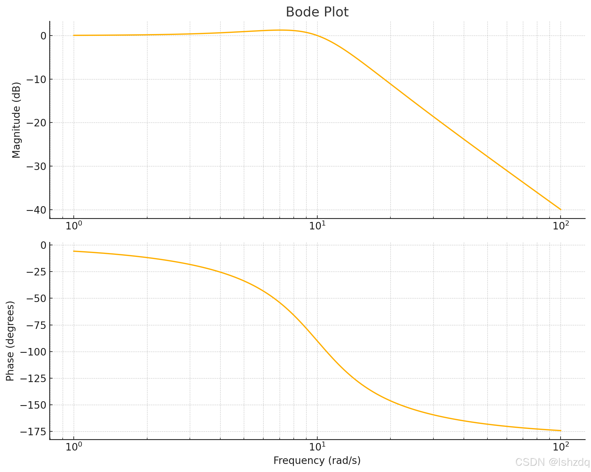
Bode 图完整介绍
Bode 图由两个部分组成:
- 幅值图 (Magnitude Plot):描述系统对不同频率输入信号的增益大小(幅值响应)。
- 相位图 (Phase Plot):描述系统输出信号相对于输入信号的相位差。
Bode 图的横轴是频率,以对数刻度显示(单位:rad/s)。纵轴则分别显示幅值(以分贝 dBdB 为单位)和相位(以角度为单位)。
相位图的完整解释
什么是相位图
相位图表示系统输出信号相对于输入信号的相位差,反映了信号的延迟或超前行为。相位的单位是角度(°),常见的范围是 [−360°,0°][-360°, 0°] 或 [−180°,180°][-180°, 180°]。
相位图的特征
-
低频段:
- 在低频区域(频率接近 0),系统的相位通常接近 0° 或一个稳定值。
- 表明此时系统几乎没有延迟,输出信号能较好地跟随输入信号。
-
中频段:
- 随着频率增加,相位开始下降。
- 如果系统包含极点或零点,会导致相位快速变化,这通常对应于系统的特征频率(如谐振频率)。
-
高频段:
- 在高频区域,相位趋于一个负的稳定值(如 −90°-90°、−180°-180° 等),反映出系统对高频信号具有较大的延迟。
实际意义
-
信号延迟和超前:
- 相位的正值表示信号超前,负值表示信号延迟。
- 控制系统中,如果相位延迟过大,可能导致系统不稳定。
-
系统动态行为:
- 相位的变化率和方向反映了系统在不同频率下的动态性能。例如,相位快速变化的区域可能是谐振频率或系统的重要特征点。
-
稳定性分析:
- 结合幅值图,可以计算增益裕度和相位裕度,判断闭环系统是否稳定。
幅值图的完整解释
什么是幅值图
幅值图描述系统对不同频率输入信号的放大或衰减程度。幅值通常以分贝 dBdB 为单位,其公式为:
其中 H(jω) 是系统的频率响应。
幅值图的特征
-
低频段:
- 在低频区域(频率接近 0),幅值通常较高,表示系统能很好地通过低频信号。
- 如果系统是稳定的低通滤波器,此时幅值接近直流增益值(例如 0 dB 或其他值)。
-
中频段:
- 中频区域的幅值可能会出现一个峰值(如果系统存在谐振)。
- 谐振频率对应幅值最大的位置。谐振频率由系统的阻尼比和自然频率决定。
-
高频段:
- 在高频区域,幅值通常下降,以一个固定的斜率递减(例如 -20 dB/decade 或 -40 dB/decade)。
- 反映出系统对高频信号的衰减特性。
实际意义
-
频率选择性:
- 幅值图显示系统对不同频率信号的放大或衰减能力。通过观察幅值图,可以判断系统是低通、高通、带通还是带阻滤波器。
-
增益分析:
- 控制系统中,幅值图用于确定增益裕度,确保系统在反馈时的稳定性。
-
噪声抑制:
- 对高频噪声的衰减程度可通过高频段的幅值特性分析。
-
动态范围:
- 幅值图可以帮助理解系统能处理的最大和最小信号幅度范围。
结合相位图和幅值图的整体意义
-
系统特征频率:
- 幅值图中谐振峰值对应的频率,通常会在相位图中表现为相位快速变化的点。这些频率是系统的特征频率。
-
稳定性判断:
- 使用幅值图和相位图可以计算系统的增益裕度和相位裕度,判断闭环系统的稳定性。
- 增益裕度:当相位为 -180° 时,幅值距离 0 dB 的距离。
- 相位裕度:当幅值为 0 dB 时,相位距离 -180° 的距离。
-
滤波性能:
- 幅值图显示系统对不同频率信号的处理能力,相位图则补充了延迟和动态行为的分析。
总结
Bode 图是控制系统和信号处理领域中最常用的工具之一,提供了频域内关于系统增益和相位的全方位信息。它直观地展示了系统如何响应不同频率的输入信号,为稳定性分析、滤波器设计和控制器优化提供了重要依据。
代码摘抄
import numpy as np
import matplotlib.pyplot as plt
from scipy import signal

# Define the transfer function
# Example: Second-order system H(s) = ω_n^2 / (s^2 + 2ζω_ns + ω_n^2)

# Parameters for the system
zeta = 0.5  # Damping ratio (controls how oscillatory the system is)
omega_n = 10  # Natural frequency (rad/s), determines the frequency of oscillation

# Numerator and denominator of the transfer function
numerator = [omega_n**2]  # The numerator of the transfer function (constant gain)
denominator = [1, 2*zeta*omega_n, omega_n**2]  # The denominator (s^2 + 2ζω_ns + ω_n^2)

# Create the transfer function
# signal.TransferFunction represents the system in the Laplace domain
system = signal.TransferFunction(numerator, denominator)

# Frequency range for the Bode plot
frequencies = np.logspace(0, 2, 500)  # From 10^0 (1 rad/s) to 10^2 (100 rad/s), 500 points

# Compute the Bode plot data
w, mag, phase = signal.bode(system, frequencies)  # Get magnitude and phase responses

# Plot the Bode magnitude and phase
plt.figure(figsize=(10, 8))  # Set the figure size

# Magnitude plot
plt.subplot(2, 1, 1)  # First subplot: Magnitude
plt.semilogx(w, mag, color='orange')  # Logarithmic x-axis for frequency, y-axis in dB
plt.title('Bode Plot')  # Plot title
plt.ylabel('Magnitude (dB)')  # y-axis label
plt.grid(True, which='both', linestyle='--', linewidth=0.5)  # Add grid lines for better readability

# Phase plot
plt.subplot(2, 1, 2)  # Second subplot: Phase
plt.semilogx(w, phase, color='orange')  # Logarithmic x-axis for frequency, y-axis in degrees
plt.ylabel('Phase (degrees)')  # y-axis label
plt.xlabel('Frequency (rad/s)')  # x-axis label
plt.grid(True, which='both', linestyle='--', linewidth=0.5)  # Add grid lines for better readability

# Adjust layout to prevent overlap between subplots
plt.tight_layout()

# Display the plots
plt.show()
Key Points:
-
System Definition:
- The transfer function is defined as H(s)=ωn2s2+2ζωns+ωn2H(s) = \frac{\omega_n^2}{s^2 + 2\zeta\omega_ns + \omega_n^2}.
- The numerator and denominator coefficients represent the system's dynamics.
-
Frequency Range:
- A logarithmic frequency range (
logspace) is chosen to visualize behavior over multiple orders of magnitude.
- A logarithmic frequency range (
-
Bode Plot:
signal.bodecomputes the magnitude (in dB) and phase (in degrees) for the specified frequency range.
-
Visualization:
- Two subplots: one for magnitude and one for phase.
semilogxis used for a logarithmic x-axis to match standard Bode plot conventions.
-
Customization:
- Grid lines (
grid) improve readability. tight_layoutensures that the labels and titles don't overlap.
- Grid lines (
You can adjust the damping ratio (zeta), natural frequency (omega_n), or even replace the transfer function to analyze different systems. Let me know if you'd like further customization!

