基于BGP跨域的组网实验
一、设计思路
边界网关协议(Border Gateway Protocol,BGP)是一种用来在路由选择域之间交换网络层可达性信息(Network Layer Reachability Information,NLRI)的路由选择协议。由于不同的管理机构分别控制着他们各自的路由选择域,因此,路由选择域经常被称为自治系统AS(Autonomous System)。现在的Internet是一个由多个自治系统相互连接构成的大网络,BGP作为事实上的Internet外部路由协议标准,被广泛应用于ISP(Internet Service Provider)之间。
IGP(Interior Gateway Protocol,内部网关协议)被设计用来在单一的路由选择域内提供可达性信息并不适合提供域间路由选择功能,BGP(Border Gateway Protocol,域间路由协议)作为优秀的域间路由协议得以产生并发展。
二、设计topo图及设计需求
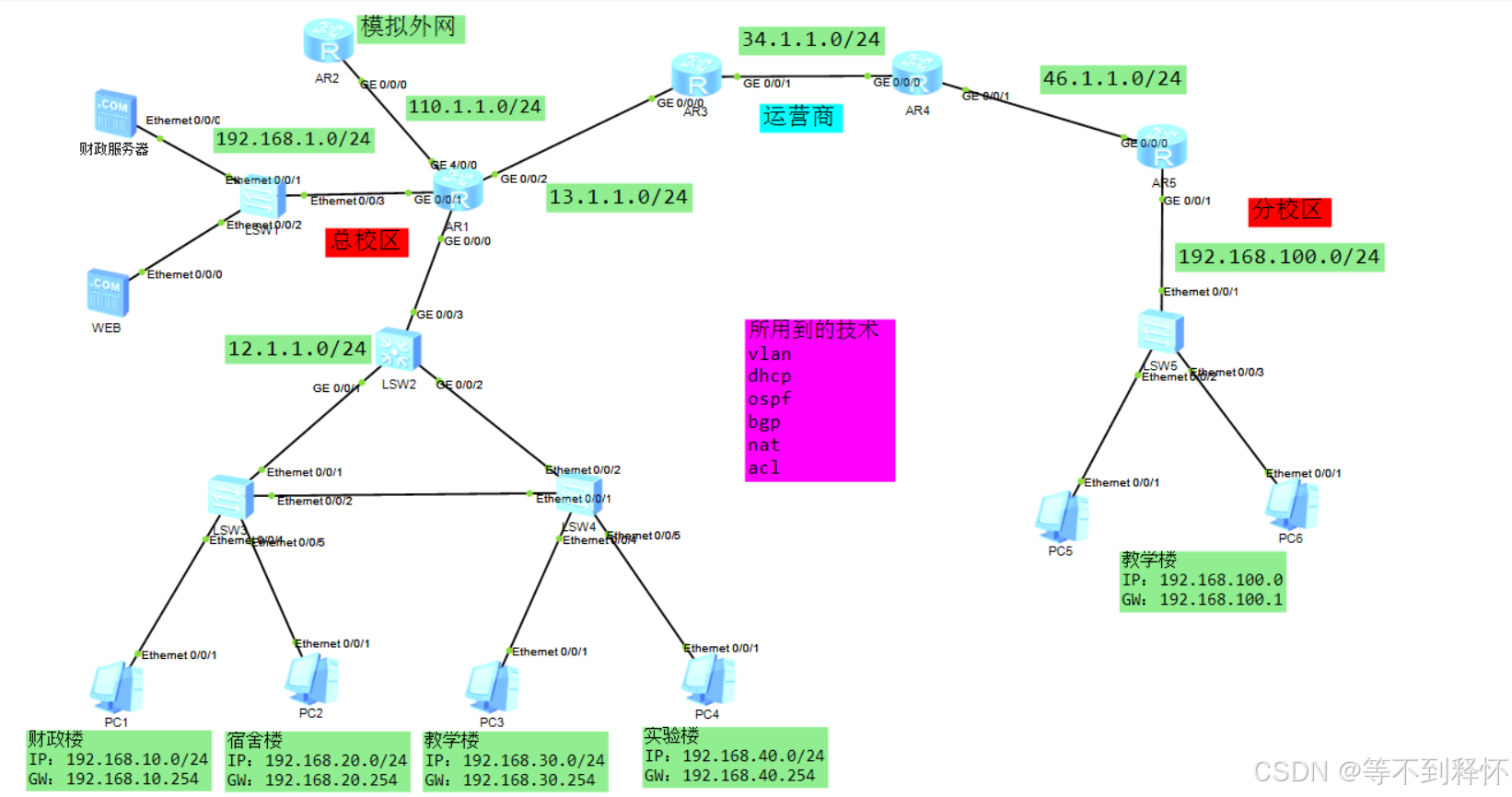
设计需求:
1.为总校区行政楼划分vlan10 网段为192.168.10.0/24,宿舍楼划分vlan 20,网段为192.168.20.0/24 ,教学楼为vlan30,网段192.168.30.0/24
实验楼 vlan40 ,网段192.168.40.0/24,分校区的教学楼vlan 100 ,网段是192.168.100.0/24
2.合理利用trunk和acces技术,明白打tag和去tag的原理
3.三层交换机配置svi口,作为pc的网关,并设置vlanif800上连公司出口路由器
4.汇聚交换机开启dhcp功能,建立地址池,全局配置dhcp功能
5.nat使用napt技术,将内网地址转换为外网地址+端口的方式,并将内网的web服务器映射出去,可供外网访问校园web服务器
6.内网使用ospf协议完成互通,运营商使用ospf模拟互通
7.总校区和运营商,运营商和分校区之间建立bgp邻居,两校区之间的流量通过bgp进行传输
8.只允许行政楼才能访问财政服务器
三、中小型企业网/校园网的设计(可不看)
插曲:中小型企业网/校园网的设计(可自行打开阅读)
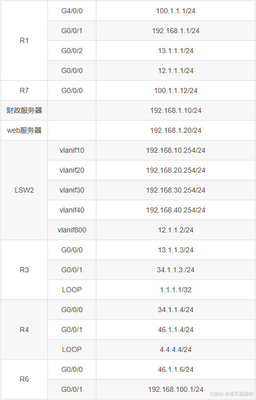
四、地址规划表
五、网络配置全过程(跟着步骤一步一步走)
1、vlan划分
            SW2:
sys
un in en
sys SW2
vlan batch 10 20 30 40 800
int G0/0/1
port link-type trunk
port trunk allow-pass vlan 10 20 30 40
int G0/0/2
port link-type trunk
port trunk allow-pass vlan 10 20 30 40
----------------------------


            SW3:
sys
un in en
sys SW3
vlan batch 10 20 30 40
int e0/0/1
port link-type trunk
port trunk allow-pass vlan 10 20 30 40
int e0/0/2
port link-type trunk
port trunk allow-pass vlan 10 20 30 40
int e0/0/4
port link-type access
port default vlan 10
int e0/0/5
port link-type access
port default vlan 20
-----------------------------


            SW4:
sys
un in en
sys SW4
vlan batch 10 20 30 40
int e0/0/1
port link-type trunk
port trunk allow-pass vlan 10 20 30 40
int e0/0/2
port link-type trunk
port trunk allow-pass vlan 10 20 30 40
int e0/0/4
port link-type access
port default vlan 30
int e0/0/5
port link-type access
port default vlan 40
-------------------------------
2、svi口配置
            SW2:
int vlan 10
ip add 192.168.10.254 24
int vlan 20
ip add 192.168.20.254 24
int vlan 30
ip add 192.168.30.254 24
int vlan 40
ip add 192.168.40.254 24
int vlan 800
ip add 12.1.1.2 24
int g0/0/3
port link-type access
port default vlan 800
--------------------------


             R1:
interface G0/0/0
 ip address 12.1.1.1 24
interface G0/0/1
 ip address 192.168.1.1 24
interface G0/0/2
 ip address 13.1.1.1 24
interface G4/0/0
 ip address 100.1.1.1 24
---------------------------


             R2:
interface G0/0/0
 ip address 100.1.1.12 24
--------------------------


            R3:
interface G0/0/0
 ip address 13.1.1.3 24
interface G0/0/1
 ip address 34.1.1.3 24
interface LoopBack0
 ip address 1.1.1.1 32
--------------------------


            R4:
interface G0/0/0
 ip address 34.1.1.4 24
interface G0/0/1
 ip address 46.1.1.4 24
interface LoopBack0
 ip address 4.4.4.4 24
-------------------------


             R5:
interface G0/0/0
 ip address 46.1.1.6 24
interface G0/0/1
 ip address 192.168.100.1 24
-------------------------
3、DHCP
            SW2:
dhcp enable
ip pool vlan10
net 192.168.10.0 mask 24
gateway-list 192.168.10.254
dns-list 8.8.8.8
int vlan10
dhcp select global
ip pool vlan20
net 192.168.20.0 mask 24
gateway-list 192.168.20.254
dns-list 8.8.8.8
int vlan20
dhcp select global
ip pool vlan30
net 192.168.30.0 mask 24
gateway-list 192.168.30.254
dns-list 8.8.8.8
int vlan30
dhcp select global
ip pool vlan40
net 192.168.40.0 mask 24
gateway-list 192.168.40.254
dns-list 8.8.8.8
int vlan40
dhcp select global
-------------------------
4、OSPF
             SW2:
ospf 1
area 0.0.0.0
network 192.168.0.0 0.0.255.255
network 12.1.1.2 0.0.0.0

             R1:
sys
un in en
sys R1
ospf 1
area 0.0.0.0
network 12.1.1.1 0.0.0.0
network 192.168.1.0 0.0.0.255
---------------------------


             R3:
sys
un in en
sys R3
ospf 1
area 0.0.0.0
network 1.1.1.1 0.0.0.0
network 34.1.1.3 0.0.0.0
---------------------------


            R4:
sys
un in en
sys R4
ospf 1
area 0.0.0.0
network 4.4.4.4 0.0.0.0
network 34.1.1.4 0.0.0.0
--------------------------
5、NAT地址转换
            R1:
acl number 2000
rule 5 permit source 192.168.0.0 0.0.255.255
nat address-group 1 100.1.1.5 100.1.1.5
interface GigabitEthernet4/0/0
ip address 100.1.1.1 255.255.255.0
nat server protocol tcp global 100.1.1.6 www inside 192.168.1.20 www
nat outbound 2000 address-group 1
---------------------------------


            SW2:
ip route-static 0.0.0.0 0.0.0.0 12.1.1.1
---------------------------------
6、BGP
            R1:
bgp 100
peer 13.1.1.3 as-number 200
ipv4-family unicast
undo synchronization
network 192.168.1.0
network 192.168.10.0
network 192.168.20.0
network 192.168.30.0
network 192.168.40.0
peer 13.1.1.3 enable
--------------------------


            R3:
bgp 200
peer 4.4.4.4 as-number 200
peer 4.4.4.4 connect-interface LoopBack0
peer 13.1.1.1 as-number 100
ipv4-family unicast
undo synchronization
peer 4.4.4.4 enable
peer 4.4.4.4 next-hop-local
peer 13.1.1.1 enable
--------------------------


            R4:
bgp 200
peer 1.1.1.1 as-number 200
peer 1.1.1.1 connect-interface LoopBack0
peer 46.1.1.6 as-number 300
ipv4-family unicast
undo synchronization
peer 1.1.1.1 enable
peer 1.1.1.1 next-hop-local
peer 46.1.1.6 enable
--------------------------


            R5:
bgp 300
peer 46.1.1.4 as-number 200
ipv4-family unicast
undo synchronization
network 192.168.100.0
peer 46.1.1.4 enable
---------------------------


            R1:
ospf 1
import-route bgp    //做引入
---------------------------
7、ACL访问控制
             R1:
acl number 3001
 rule 5 permit icmp source 192.168.10.0 0.0.0.255 destination 192.168.1.10 0
 rule 10 deny icmp
interface GigabitEthernet0/0/1
 traffic-filter outbound acl 3001
----------------------------
六、测试部分
需你联系本作者自行获取