主要信息来自官网
Getting Started — SchemDraw 0.14 documentation
1. 了解元器件
基本元件:阻容感,开关,插座,运放,电缆,变压器,基本够用了?
库里的芯片: 逻辑芯片,数码管, DIP封装片,预定义芯片
连接器:单排,双排,跳线帽,DB头,数据总线,电源插座
组合原件:光耦,继电器,桥堆
逻辑电路: 门电路,组合逻辑, 真值表,
时序图: 信号时序
信号处理:可以认为来表示DSP的处理能力
流程图及框图:流程图,连接线,状态图,决策图,
电路库及其丰富,包括电路示意图等等
2. 基本操作
place 放置元件
with schemdraw.Drawing() as d:
    d += elm.Capacitor()
    d += elm.Resistor()
    d += elm.Diode()
输出:
方向选择, 放置时增加方向的methods就可以改变防止方向,并且直到下次改变
    d += elm.Capacitor()
    d += elm.Resistor().up()
    d += elm.Resistor()
    d += elm.Diode().right()
输出结果:
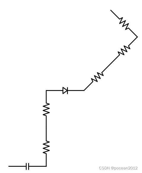
theta方法可以设置偏转角度并保持,注意这里角度是绝对值:
    d += elm.Capacitor()
    d += elm.Resistor().up()
    d += elm.Resistor()
    d += elm.Diode().right()

    d +=elm.Resistor().theta(45)
    d +=elm.Resistor()
    d +=elm.Resistor().theta(135)
3. 各种连接方式
按方向(up,down,lef,right),按起点终点(at, to), 按端口,按x,y(tox,toy), 封闭(endpoints)
多连接, dot, push,pop
指定位置:drop, hold, here
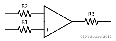
at方法指定器件起始端连接引脚
    d += (opamp := elm.Opamp())

    d += elm.Resistor().left().at(opamp.in2).label("R1")
    d += elm.Resistor().at(opamp.in1).label("R2")
    d += elm.Resistor().right().at(opamp.out).label("R3")
dot方法打连接点, length方法增加长度
    d += elm.Dot()
    d += elm.Resistor()
    d += elm.Dot()
    d += elm.Diode().length(6)
    d += elm.Dot()
to方法指定末端连接位置
    R = d.add(elm.Resistor())
    C = d.add(elm.Capacitor().up())
    Q = d.add(elm.Diode().to(R.start))
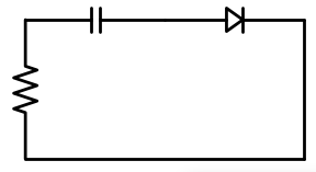
tox和toy方法用于划线到指定位置,其实是to x 和to y
        d += (C := elm.Capacitor())
        d += elm.Diode()
        d += elm.Line().down()
        d += elm.Line().tox(C.start) # line to the x value of start of C
        d += elm.Resistor().up()
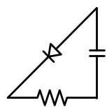
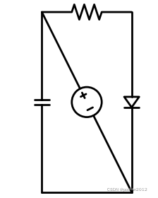
endpoints方法更直接,在两个指定端点之间放置元件
        d += (R := elm.Resistor())
        d += (Q := elm.Diode().down(6))
        d += elm.Line().tox(R.start)
        d += elm.Capacitor().toy(R.start)
        d += elm.SourceV().endpoints(Q.end, R.start)
控制翻转: flip 左右, reverse 上下
        d += (opamp := elm.Opamp())
        d += elm.Zener().left().label('Normal').at(opamp.in1)
        d += elm.Zener().left().flip().label('Flip').at(opamp.in2)
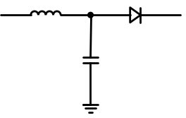
push和pop方法用于配置绘制方向,可在连接点用于多个方向连接时的绘制
        d += elm.Inductor()
        d += elm.Dot()

        d.push()  # Save this drawing position/direction for later

        d += elm.Capacitor().down()  # Go off in another direction temporarily
        d += elm.Ground(lead=False)


        d.pop()   # Return to the pushed position/direction

        d += elm.Diode()
drop & hold 保持不移动
        d += elm.Diode()  # Normal placement: drawing position moves to end of element
        d += elm.Dot().color('red')

        d.here = (0, -1)
        d += elm.Diode().hold()  # Hold method prevents position from changing
        d += elm.Dot().color('blue')
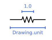
一个元件的位置坐标值为1
疑问: 网格是怎么定义的?
3. 配置参数,设置label
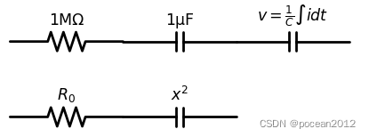
表达方式:label支持utf-8格式的字符串, 支持LaTeX数学公式表达方式
数学表达式的具体表达,可参考如下连接
Writing mathematical expressions — Matplotlib 3.5.1 documentation
with schemdraw.Drawing() as d:
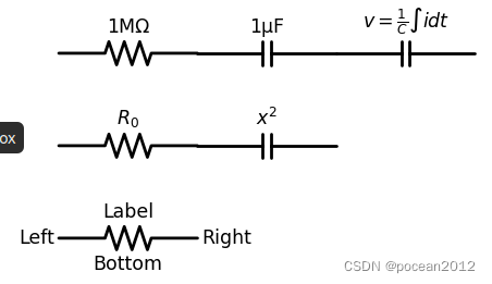
    d += elm.Resistor().label('1MΩ')
    d += elm.Capacitor().label('1μF')
    d += elm.Capacitor().label(r'$v = \frac{1}{C} \int i dt$')
    d += elm.Resistor().at((0, -2)).label('$R_0$')
    d += elm.Capacitor().label('$x^2$')
放置位置, loc:top, bottom,right, left
    d += elm.Resistor().label('1MΩ')
    d += elm.Capacitor().label('1μF')
    d += elm.Capacitor().label(r'$v = \frac{1}{C} \int i dt$')
    d += elm.Resistor().at((0, -2)).label('$R_0$')
    d += elm.Capacitor().label('$x^2$')
    # label for location

    d += (elm.Resistor().at((0,-4))
        .label('Label')  # 'top' is default
        .label('Bottom', loc='bottom')
        .label('Right', loc='right')
        .label('Left', loc='left'))
放置位置也可以跟随角点走
    # label for value
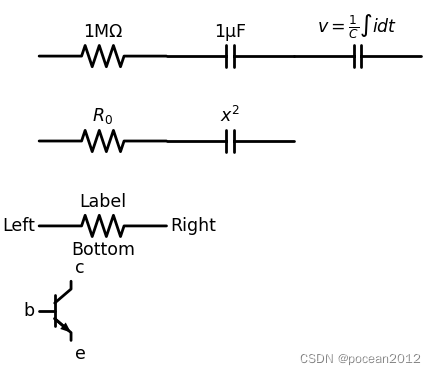
    d += elm.Resistor().label('1MΩ')
    d += elm.Capacitor().label('1μF')
    d += elm.Capacitor().label(r'$v = \frac{1}{C} \int i dt$')
    d += elm.Resistor().at((0, -2)).label('$R_0$')
    d += elm.Capacitor().label('$x^2$')
    # label for location

    d += (elm.Resistor().at((0,-4))
        .label('Label')  # 'top' is default
        .label('Bottom', loc='bottom')
        .label('Right', loc='right')
        .label('Left', loc='left'))

    d += (elm.BjtNpn().at((0,-6))
        .label('b', loc='base')
        .label('c', loc='collector')
        .label('e', loc='emitter'))
也可以控制label的走向,位移,字体,排版和颜色
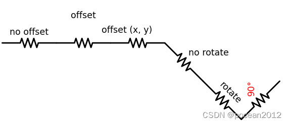
    d += elm.Resistor().label('no offset').at((0,-10))
    d += elm.Resistor().label('offset', ofst=1)
    d += elm.Resistor().label('offset (x, y)', ofst=(-.6, .2))
    d += elm.Resistor().theta(-45).label('no rotate')
    d += elm.Resistor().theta(-45).label('rotate', rotate=True)
    d += elm.Resistor().theta(45).label('90°', rotate=90, color="red")
电压类的label, 可以用gap元素来作为截断点
   # label for gap
    d += elm.Line().dot(open=True)
    d += elm.Gap().label(('–','$V_o$','+'))
    d += elm.Line().idot(open=True)
电流箭头label ,加reverse()方法可以调转方向
# label for voltage
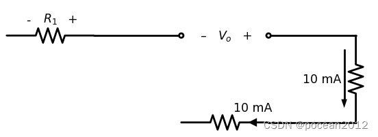
    d += elm.Resistor().label(('-','$R_1$','+'))

    # label for gap
    d += elm.Line().dot(open=True)
    d += elm.Gap().label(('–','$V_o$','+'))
    d += elm.Line().idot(open=True)

    R1 = d.add(elm.Resistor().down())
    d += elm.CurrentLabel().at(R1).label('10 mA').reverse()
线内的电流箭头:
# label for voltage
    d += elm.Resistor().label(('-','$R_1$','+'))

    # label for gap
    d += elm.Line().dot(open=True)
    d += elm.Gap().label(('–','$V_o$','+'))
    d += elm.Line().idot(open=True)

    R1 = d.add(elm.Resistor().down())
    d += elm.CurrentLabel().at(R1).label('10 mA').reverse()

    d+=elm.Line(3).left()
    R2 = d.add(elm.Resistor().left())
    d += elm.CurrentLabelInline(direction='in').at(R2).label('10 mA')
Loop Current 电流环
    # loop current
    R1 = d.add(elm.Resistor().label("R1"))
    C1 = d.add(elm.Capacitor().label("C1").down())
    D1 = d.add(elm.Diode().label("D1",loc='bottom').fill(True).left())
    L1 = d.add(elm.Inductor().label("L1").up())
    d += elm.LoopCurrent([R1, C1, D1, L1], direction='cw').label('$I_1$')
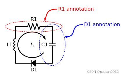
非常贴心的功能,批注Annotations
# loop current
    R1 = d.add(elm.Resistor().label("R1"))
    C1 = d.add(elm.Capacitor().label("C1").down())
    D1 = d.add(elm.Diode().label("D1",loc='bottom').fill(True).left())
    L1 = d.add(elm.Inductor().label("L1").up())
    d += elm.LoopCurrent([R1, C1, D1, L1], direction='cw').label('$I_1$')

    parallel = d.add(elm.Encircle([R1], padx=.8).linestyle('--').linewidth(1).color('red'))
    series = d.add(elm.Encircle([C1], padx=.8).linestyle('--').linewidth(1).color('blue'))

    d += elm.Annotate().at(parallel.NNE).delta(dx=1, dy=1).label('R1 annotation').color('red')
    d += elm.Annotate(th1=0).at(series.ENE).delta(dx=1.5, dy=1).label('D1 annotation').color('blue')
4. style 样式
元件样式包括: color, fill, linewidth ,linestyle ,未单独定义情况下,数值来自global defaults缺省值
with schemdraw.Drawing(color='blue', fill='lightgray') as d:


# All elements are blue with lightgray fill unless specified otherwise


    d += elm.Diode()
    d += elm.Diode().fill('red')        # Fill overrides drawing color here
    d += elm.Resistor().fill('purple')  # Fill has no effect on non-closed elements
    d += elm.RBox().linestyle('--').color('orange')
    d += elm.Resistor().linewidth(5)
config方法可以定义全局样式
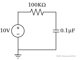
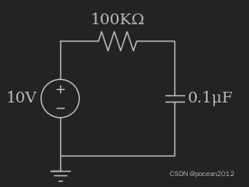
schemdraw.config(lw=1, font='serif')
with schemdraw.Drawing() as d:
d += elm.Resistor().label('100KΩ')
d += elm.Capacitor().down().label('0.1μF', loc='bottom')
d += elm.Line().left()
d += elm.Ground()
d += elm.SourceV().up().label('10V')
设置风格(背景? )
Themes
Schemdraw also supports themeing, to enable dark mode, for example. The defined themes match those in the Jupyter Themes package:
default (black on white)
dark (white on black)
solarizedd
solarizedl
onedork
oceans16
monokai
gruvboxl
gruvboxd
grade3
chesterish
测试了几个样式 .....
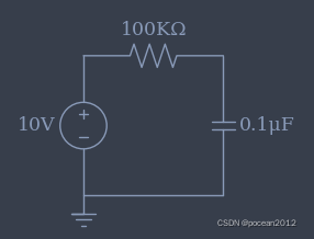
onedork
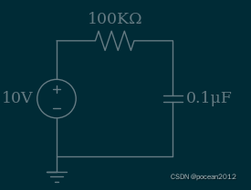
solarizedd
monokai
5. backend 相当于画布canvas
就是两样: matplotlib和SVG, 默认matplotlib, 配置成svg可以直接被网页引用,更方便,尤其是不需要单独调入字体。
选择依据,参见官方说明:
Reasons to choose the SVG backend include:
No Matplotlib/Numpy dependency required (huge file size savings if bundling an executable).
Speed. The SVG backend draws 4-10x faster than Matplotlib, depending on the circuit complexity.
Reasons to use Matplotlib backend:
To customize the schematic after drawing it by using other Matplotlib functionality.
To render directly in other, non-SVG, image formats, with no additional code.
5. 常用模块电路
- Analog Circuits
- Opamp Circuits
- Digital Logic
- Timing Diagrams
- Solid State
- Integrated Circuits
- Signal Processing
- Flowcharting
- Styles
6. 定制部件
群组复制
7. 输出SVG图片
加入backend定义:
with schemdraw.Drawing(backend="svg") as d:
然后用d.save(path)来保存svg图片


