仿真系统简介
机器人的开发需要很多的测试。而测试就需要搭建场地。测试项目一多,需要的场地的形式也会更多。搭建这样的场地不仅成本高,耗费的人力和物力都相当可观。有些场景在真实环境中不容易出现,但却可以在仿真环境中制造出来。
通过对静态环境的模拟和动态环境的模拟,仿真系统可以帮助开发人员和测试人员触及到很多长尾的情况。而做到这些的代价要比在真实环境中的测试低很多,效率也更高。不管是服务机器人领域还是自动驾驶,仿真技术已经成为一项不可或缺的关键技术。这里对仿真系统做如下简单的定义以方便大家有个整体的概念。
1)仿真系统是通过计算机仿真技术对真实环境的数学建模。它需要模拟重力,碰撞,摩擦,机器人的动力学等等基础物理现象。
2)仿真技术的基本原理是在仿真场景内,将真实控制器变成算法,结合传感器仿真等技术,完成对算法的测试和验证。
仿真软件
目前ROS中存在webots、gazebo、stage三种仿真环境。
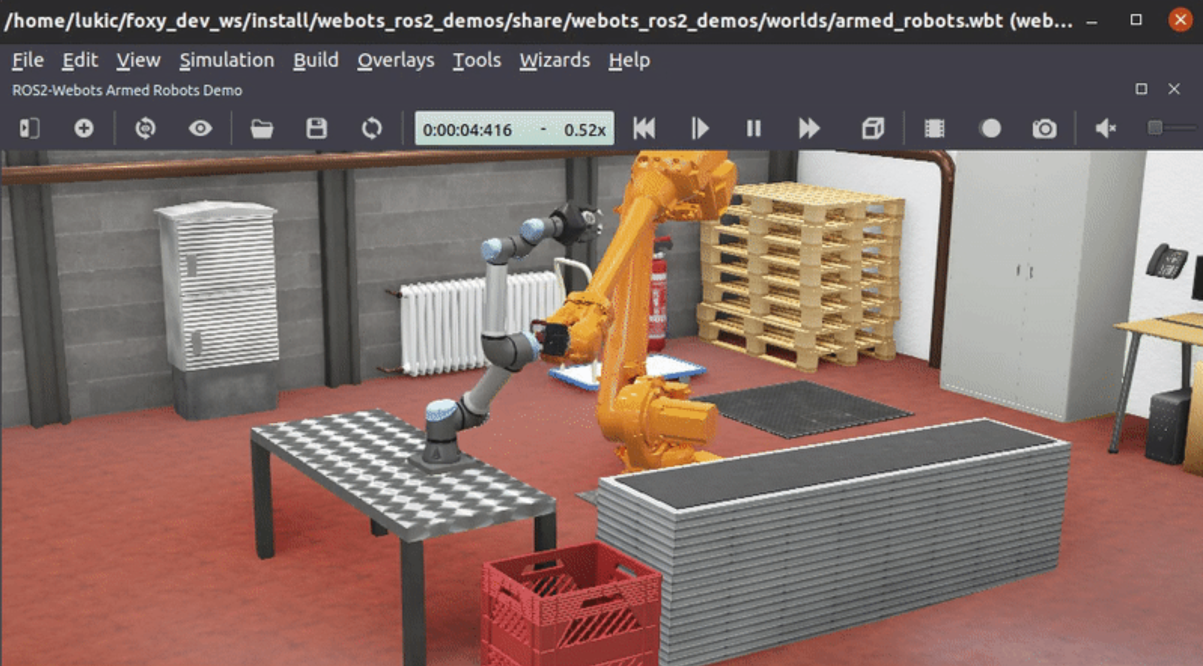
Webots
Webots 是一个开源的三维移动机器人模拟器,它与gazebo类似都是ros中仿真环境。webots在2018年以前是一款商业软件,商业软件的好处就是安装简单,在windows和ubuntu上都可以实现一键安装,对用户很友好,webots从2018年以后webots进行了开源(自2018年12月起,Webots作为开放源码软件在Apache 2.0许可下发布。)。
Webots支持C/C++、Python、MATLAB、Java、ROS和TCP/IP等多种方式实现模型的仿真控制。Webots内置了接近100种机器人模型,包括轮式机器人、人形机器人、爬行移动机器人、单臂移动机器人、双臂移动机器人、无人机、大狗、飞艇等等,其中就包括大家比较熟悉的Boston Dynamics Atlas、DJI Mavic 2 PRO、Nao、PR2、YouBot、UR、Turtlebot3 Burger等机器人。当然还有我们需要的自动驾驶环境,webots还提供有火星车的模型可以让大家使用。
Webots的一些关键功能包括:
- 跨平台(
Windows,Linux和Mac)。 - 稳定的物理引擎。
- 可重现性。
- 使用基于物理的渲染获得逼真的图像的高效渲染引擎。
- 简单直观的用户界面。
- 模拟各种传感器和执行器可供选择并可以工作。
- 可用的机器人模型范围很广,可以投入使用。
- 范围广泛的文件样本。
目前Webots是通过webots_ros2功能包来和ROS2集成的。
下载安装包:
wget https://ghproxy.com/https://github.com/cyberbotics/webots/releases/download/R2021a/webots_2021a_amd64.deb
系统要求:
1)至少具有2GHz双核CPU时钟速度和2 GBRAM的PC或Mac。
2)需要一个支持NVIDIA或 AMD OpenGL(最低版本 3.3)的图形适配器,至少有 512 MB 的 RAM。不推荐任何其他图形适配器,包括 Intel 图形适配器,因为它们通常缺乏良好的 OpenGL 支持,这可能会导致 3D 渲染问题和应用程序崩溃。尽管如此,在某些情况下,安装最新的英特尔显卡驱动程序可以解决此类问题,能够使用 Webots。但是。webots官方不做任何保证。对于 Linux 系统,只推荐使用 NVIDIA 显卡。Webots 在最新的 Apple 计算机中包含的所有图形卡上都运行良好。
3)Webots 不能在早于16.04的Ubuntu版本上运行,但仅提供适用于Ubuntu 18.04 和20.04的软件包。
注意:
这里使用安装包安装的方式。在r2021b这个版本,为了简化安装包大小,将很多离线模型都从安装包中直接取消。变成了用什么下载什么的模式。这样的好处是下载安装方便,但是当要用到一些模型的时候,下载就会很麻烦。可能需要半个小时才能下载好一些模型文件(取决于网络环境)。因此这里推荐安装R2021a这个版本。
webots + ros2 示例演示
参考:
https://github.com/cyberbotics/webots_ros2/wiki/Navigate-TurtleBot3
ros2 launch webots_ros2_turtlebot robot_launch.py
export TURTLEBOT3_MODEL='burger'
ros2 launch turtlebot3_navigation2 navigation2.launch.py \
    use_sim_time:=true \
    map:=$(ros2 pkg prefix webots_ros2_turtlebot --share)/resource/turtlebot3_burger_example_map.yaml
Gazebo
Gazebo是一款功能强大的三维物理仿真平台,具备强大的物理引擎、高质量的图形渲染、方便的编程与图形接口,最重要的是其开源免费的特性。
Gazebo中的机器人模型与Rviz使用的模型相同,但是需要在模型中加入机器人和周围环境的物理属性,例如质量、摩擦系数、弹性系数等。机器人的传感器信息也可以通过插件的形式加入仿真环境,以可视化的方式进行显示。
Gazebo是一款优秀的开源物理仿真环境,它具备如下特点:
动力学仿真:支持多种高性能的物理引擎,例如ODE、Bullet、SimBody、DART等。
三维可视化环境:支持显示逼真的三维环境,包括光线、纹理、影子。
传感器仿真:支持传感器数据的仿真,同时可以仿真传感器噪声。
可扩展插件:用户可以定制化开发插件,扩展gazebo的功能,满足个性化的需求。
多种机器人模型:官方提供PR2、Pioneer2 DX、TurtleBot等机器人模型,当然也可以使用自己创建的机器人模型。
TCP/IP传输:gazebo可以实现远程仿真,后台仿真和前台显示通过网络通信。
云仿真:gazebo仿真可以在Amazon、Softlayer等云端运行,也可以在自己搭建的云服务器上运行。
终端工具:用户可以使用gazebo提供的命令行工具在终端实现仿真控制。
Gazebo 也是由开源机器人基金会 (OpenSource Robot Foundation,OSRF)维护。所以他的版本发布通常是和ROS版本对应的。比如现在的ROS2 Galactic 版本对应的Gazebo版本为11。
Gazebo通过gazebo_ros_pkgs 功能包与ROS集成。
gazebo_ros_pkgs是一系列包。如下:
-
gazebo_dev:开发Gazebo插件的依赖 -
gazebo_msgs:定义了ROS2和Gazebo之间的数据接口定义,主要是Topic/Service的自定义数据结构。 -
gazebo_ros:提供了一些方便自定义插件调用的函数和类,同时也提供一些测试程序。 -
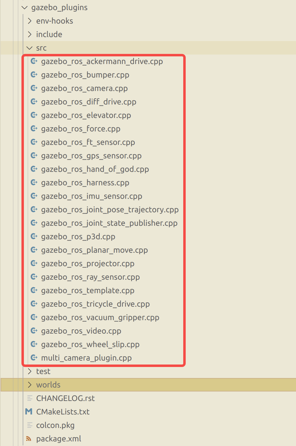
gazebo_plugins:一系列Gazebo插件,模拟传感器和控制器并与ROS进行数据对接。如果想自定义一些功能就可以在这里编写自己的插件。
关于插件的配置可以参考上面worlds目录中的示例。
gazebo + ros2 示例演示
可以参考之前的文章安装好turtlebot3。
ros2 launch turtlebot3_gazebo turtlebot3_world.launch.py
ros2 launch turtlebot3_navigation2 navigation2.launch.py use_sim_time:=True
gazebo 官方教程:
http://www.gazebosim.cn/tutorials.html
Gazebo的简单操作
安装gazebo
参考:
http://www.gazebosim.cn/tutorials_install_ubuntu.html?tut=install_ubuntu&cat=install
- 设置计算机让其接受来自
packages.osrfoundation.org的软件包.
sudo sh -c 'echo "deb http://packages.osrfoundation.org/gazebo/ubuntu-stable `lsb_release -cs` main" > /etc/apt/sources.list.d/gazebo-stable.list'
- 设置密钥
wget https://packages.osrfoundation.org/gazebo.key -O - | sudo apt-key add -
- 更新软件库
sudo apt-get update
- 安装
gazebo
sudo apt-get install gazebo11
# 对于Gazebo开发者还需要安装libgazebo11-dev软件包
sudo apt-get install libgazebo11-dev
- 安装
gazebo的ros相关包(这里安装的包对于ROS2 Galactic版本)
sudo apt install ros-galactic-gazebo-*
- 运行
gazebo
gazebo
或者运行差速小车demo
gazebo /opt/ros/galactic/share/gazebo_plugins/worlds/gazebo_ros_diff_drive_demo.world
Gazebo软件界面介绍
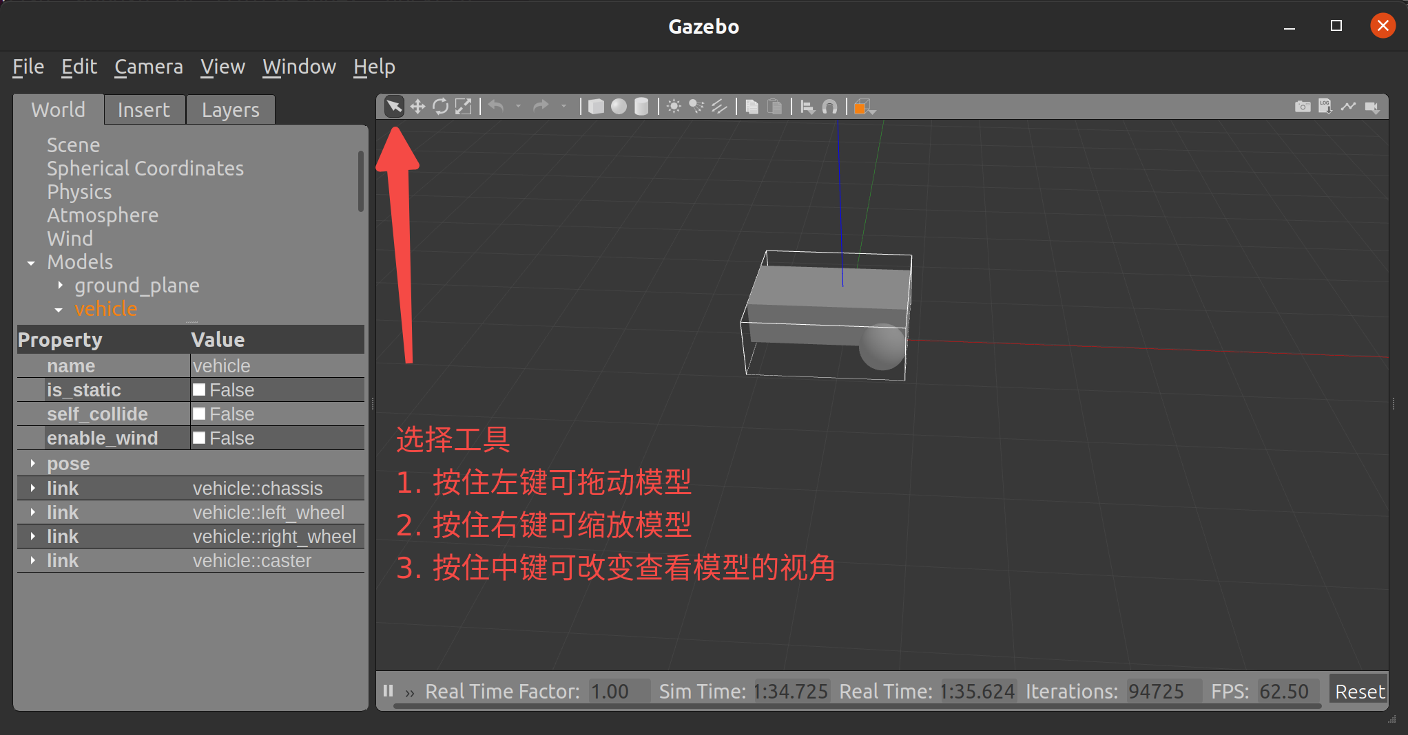
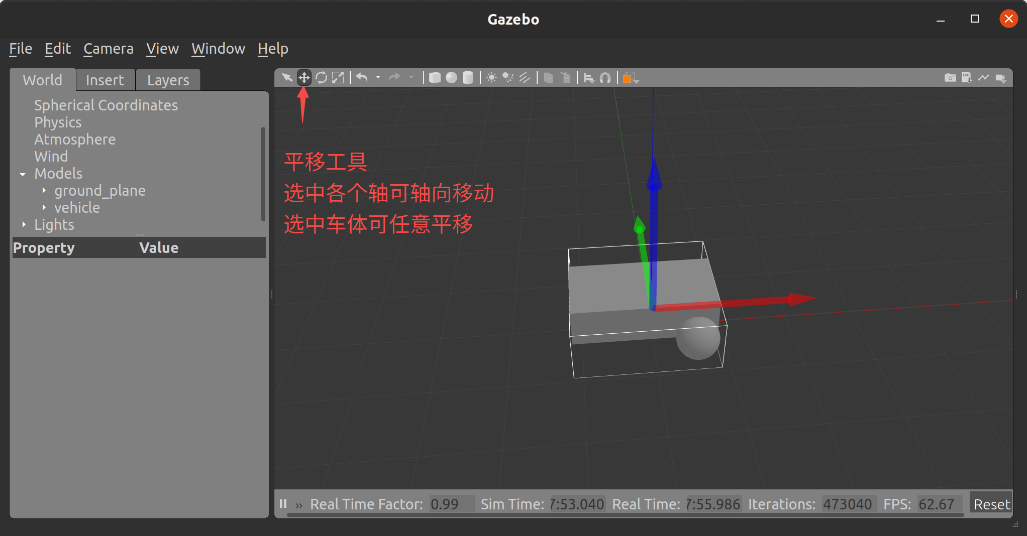
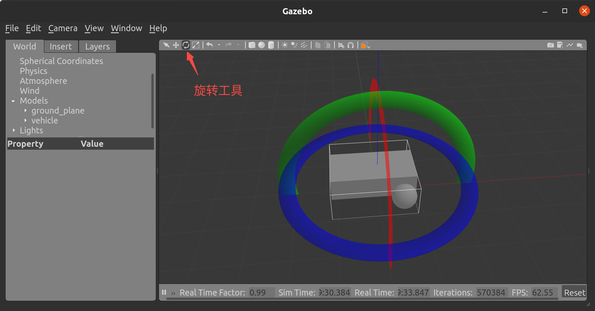
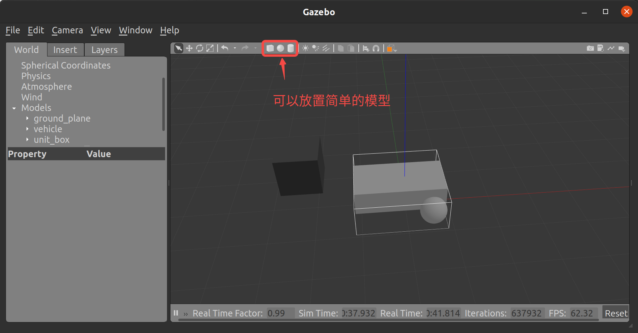
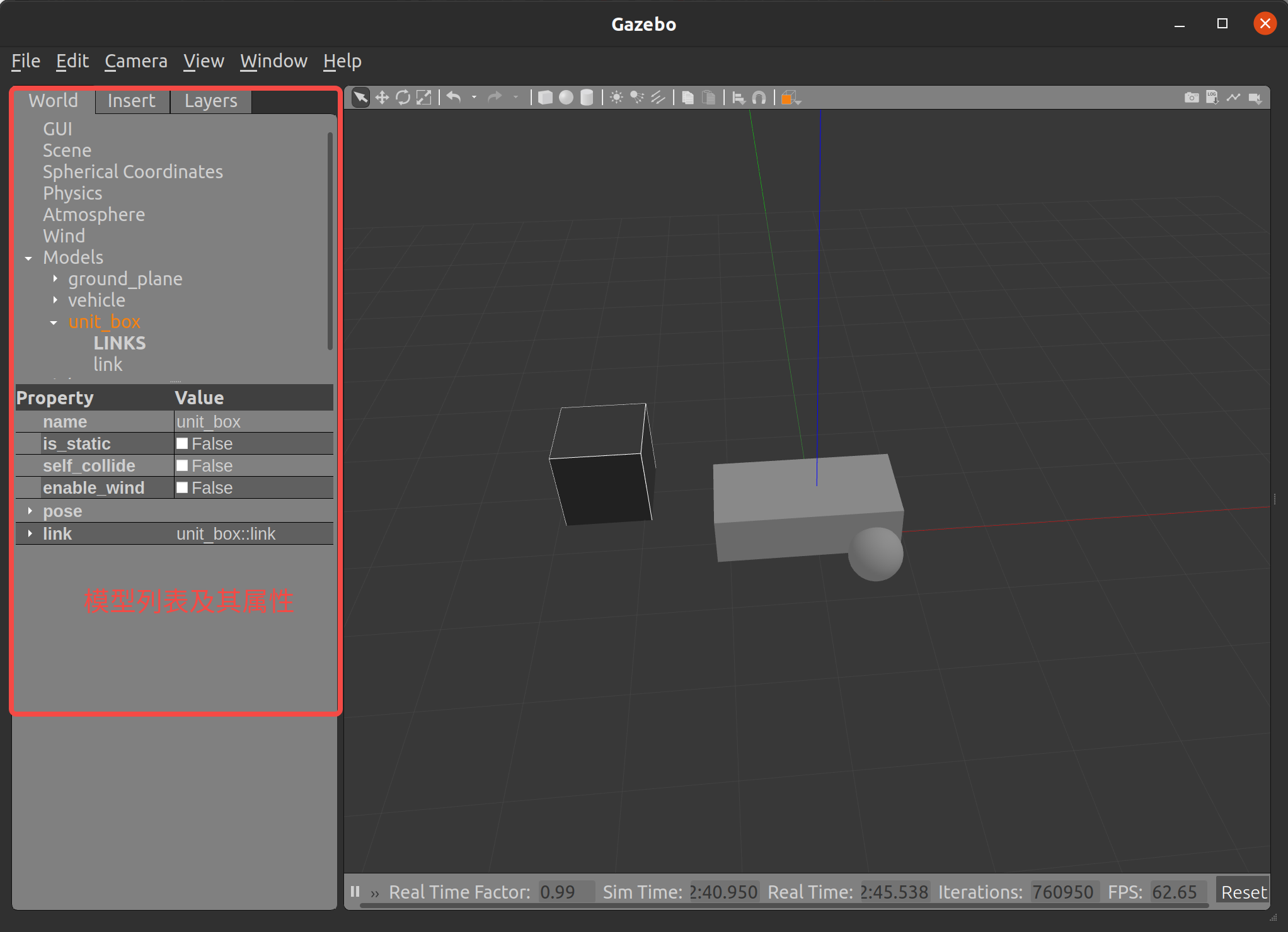
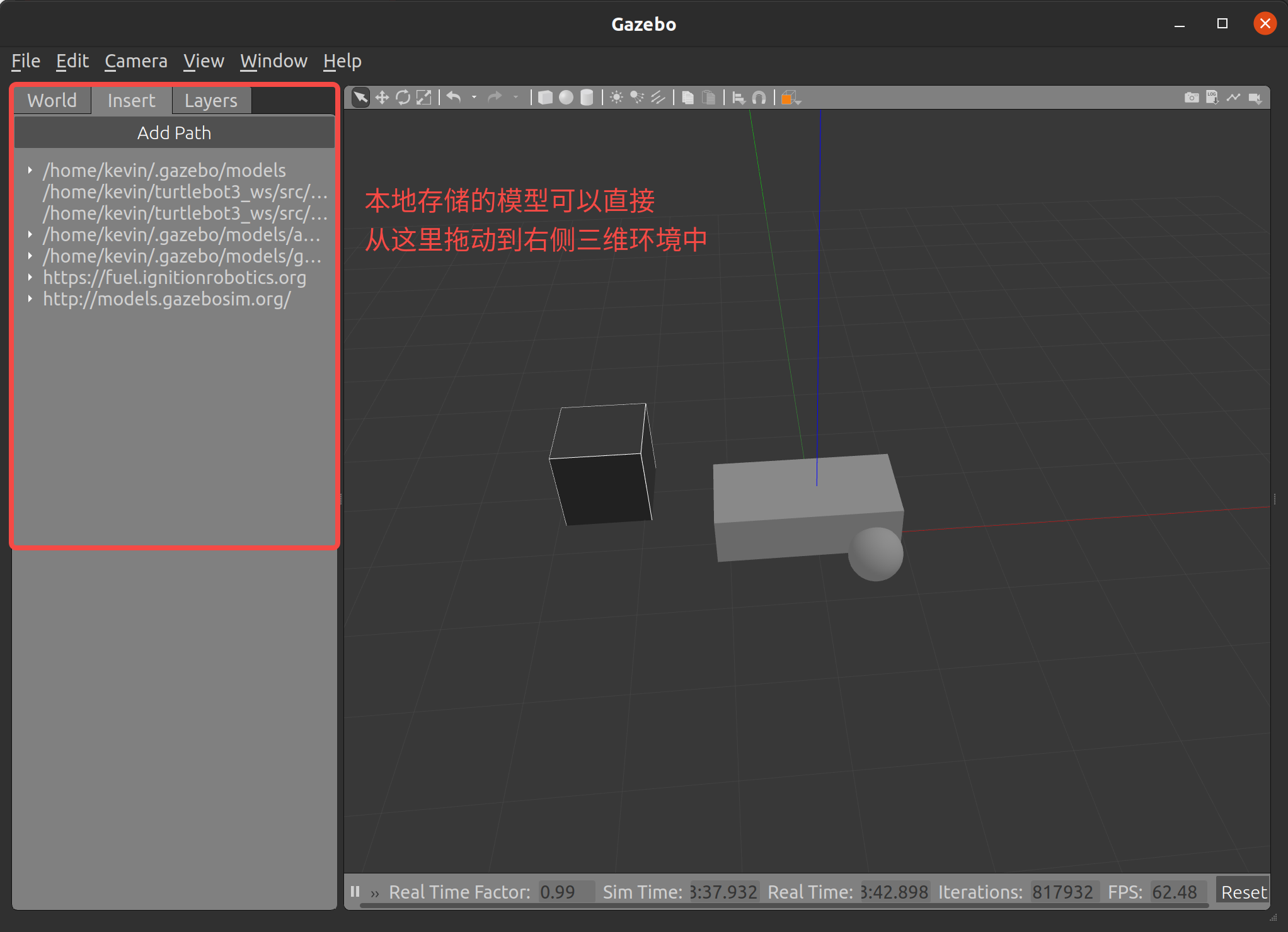
Gazebo的界面总体来讲比较简洁。下面简单介绍一下常用的功能。
主界面
Gazebo的模型默认存储在~/.gazebo文件夹中。可以通过修改GAZEBO_MODEL_PATH环境变量添加更多的模型路径。比如在~/.bashrc中添加下面的语句
export GAZEBO_MODEL_PATH=$GAZEBO_MODEL_PATH:~/turtlebot3_ws/src/turtlebot3/turtlebot3_simulations:~/turtlebot3_ws/src/turtlebot3/turtlebot3_simulations/turtlebot3_gazebo/models:~/.gazebo/models/addison_models:~/.gazebo/models/gazebo_models
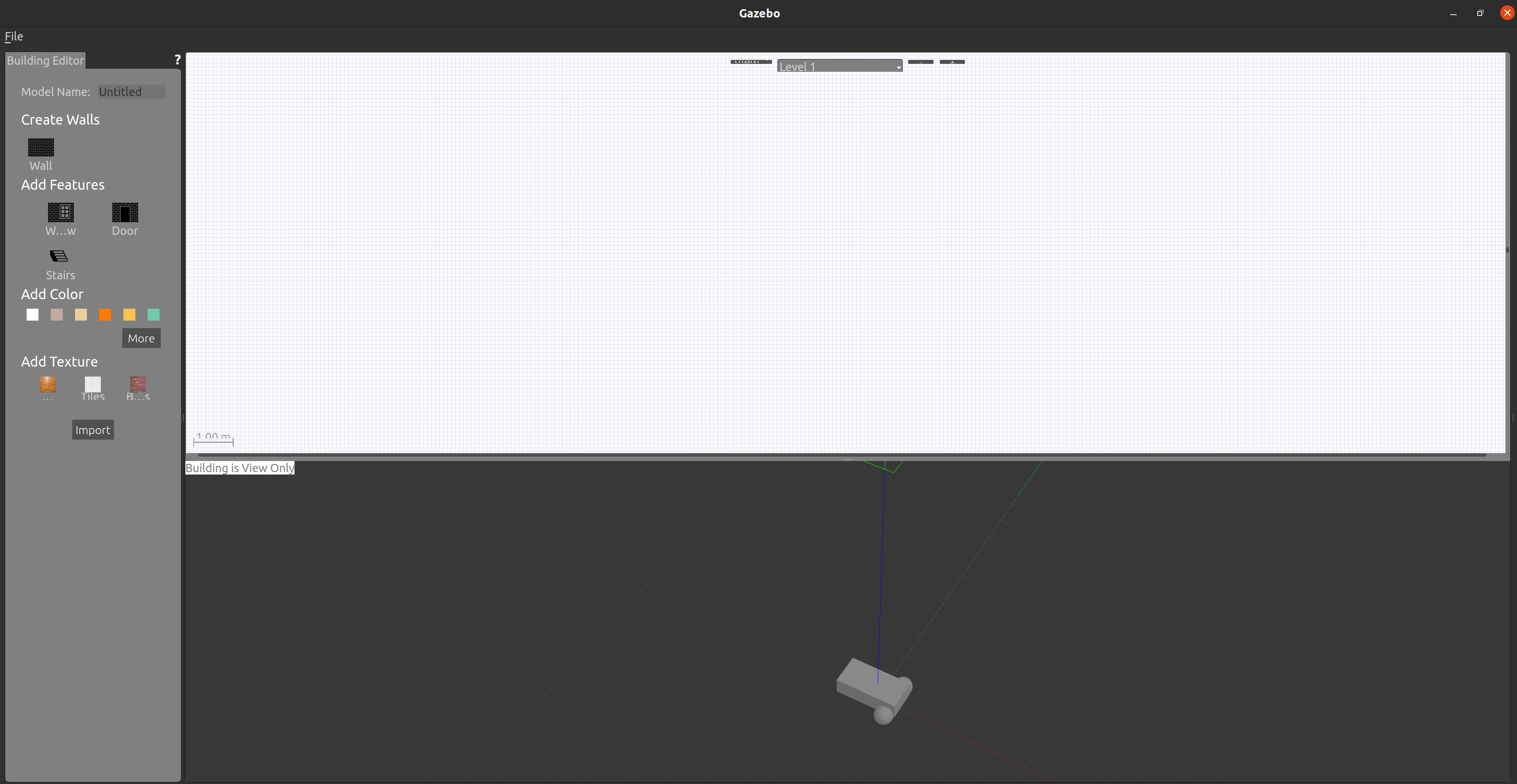
building editor
在这里可以绘制简单的环境模型,但无法绘制曲线。
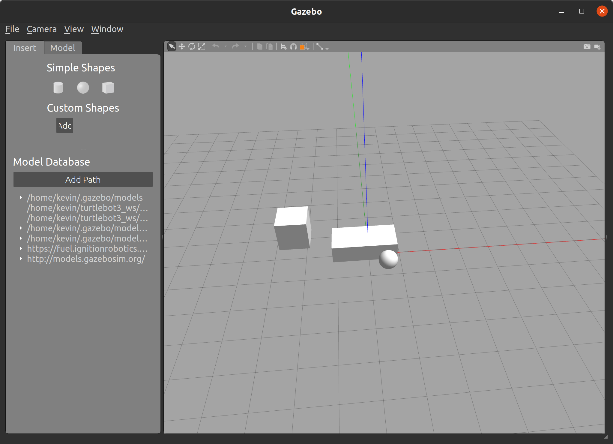
model editor
这里可以绘制基本的规则模型,但复杂的模型通常还是用专业的三维软件导出来。然后修改成gazebo能识别的文件。下面会着重介绍。
仿真模型描述文件
world文件
gazebo的仿真环境配置会保存为world后缀的文件。world文件其实是sdf语言书写的文件。里面包含了对三维环境的描述。下面是一个简单的示例:
<?xml version="1.0"?>
<sdf version="1.6">
  <world name="default">

    <include>
      <uri>model://ground_plane</uri>
    </include>

    <include>
      <uri>model://sun</uri>
    </include>

    <scene>
      <shadows>false</shadows>
    </scene>

    <gui fullscreen='0'>
      <camera name='user_camera'>
        <pose frame=''>0.319654 -0.235002 9.29441 0 1.5138 0.009599</pose>
        <view_controller>orbit</view_controller>
        <projection_type>perspective</projection_type>
      </camera>
    </gui>

    <physics type="ode">
      <real_time_update_rate>1000.0</real_time_update_rate>
      <max_step_size>0.001</max_step_size>
      <real_time_factor>1</real_time_factor>
      <ode>
        <solver>
          <type>quick</type>
          <iters>150</iters>
          <precon_iters>0</precon_iters>
          <sor>1.400000</sor>
          <use_dynamic_moi_rescaling>1</use_dynamic_moi_rescaling>
        </solver>
        <constraints>
          <cfm>0.00001</cfm>
          <erp>0.2</erp>
          <contact_max_correcting_vel>2000.000000</contact_max_correcting_vel>
          <contact_surface_layer>0.01000</contact_surface_layer>
        </constraints>
      </ode>
    </physics>

    <model name="turtlebot3_world">
      <static>1</static>
      <include>
        <uri>model://turtlebot3_world</uri>
      </include>
    </model>

  </world>
</sdf>
其中model标签就是包含了一个其他的模型,这里是turtlebot3_world模型。其他标签则描述了三维环境的一些物理特性。
URDF
URDF(Unified Robot Description Format)在ROS中是一种功能强大且标准化的机器人描述格式,但依然缺少许多功能。例如,
URDF只能单独定义单个机器人的运动学和动力学特性;- 无法定义机器人本身在世界中的姿态;
- 不能定义闭链结构(并联机器人);
- 缺乏摩擦和等更丰富的动力学特性;
- 不能定义非机器人物体,例如灯光,高度图等。
在实现方面,URDF语法大量使用XML的属性特性,使得URDF更加不灵活。 也没有向后兼容的机制。
URDF是ROS的原生支持格式,但在某些情况下(尤其是Gazebo仿真时),使用SDF格式会更加合理。
ROS中可以加载urdf文件来建立整个系统的tf树。加载方法可参考下面的launch文件。
示例来源于turtlebot3/turtlebot3_bringup/launch/turtlebot3_state_publisher.launch.py。
import os

from ament_index_python.packages import get_package_share_directory
from launch import LaunchDescription
from launch.actions import DeclareLaunchArgument
from launch.substitutions import LaunchConfiguration
from launch_ros.actions import Node
from launch_ros.substitutions import FindPackageShare


def generate_launch_description():
    TURTLEBOT3_MODEL = os.environ['TURTLEBOT3_MODEL']

    use_sim_time = LaunchConfiguration('use_sim_time', default='false')
    urdf_file_name = 'turtlebot3_' + TURTLEBOT3_MODEL + '.urdf'

    print("urdf_file_name : {}".format(urdf_file_name))

    urdf = os.path.join(
        get_package_share_directory('turtlebot3_description'),
        'urdf',
        urdf_file_name)

    # Major refactor of the robot_state_publisher
    # Reference page: https://github.com/ros2/demos/pull/426
    with open(urdf, 'r') as infp:
        robot_desc = infp.read()

    rsp_params = {'robot_description': robot_desc}

    # print (robot_desc) # Printing urdf information.

    return LaunchDescription([
        DeclareLaunchArgument(
            'use_sim_time',
            default_value='false',
            description='Use simulation (Gazebo) clock if true'),
        Node(
            package='robot_state_publisher',
            executable='robot_state_publisher',
            output='screen',
            parameters=[rsp_params, {'use_sim_time': use_sim_time}])
    ])
xacro
xacro文件是urdf文件的改进版,urdf文件只能在rviz等软件中显示,不能在仿真器中显示出来。 xacro文件可以在gazebo仿真器中显示出来,相对urdf文件,xacro文件增加了更多的属性设置标签。
xacro文件也支持定义函数,一定程序上减少了代码重复。
SDF
SDF是一种XML格式,能够描述机器人、静态和动态物体、照明、地形甚至物理学的各方面的信息。SDF可以精确描述机器人的各类性质,除了传统的运动学特性之外,还可以为机器人定义传感器、表面属性、纹理、关节摩擦等;SDF还提供了定义各种环境的方法。包括环境光照、地形等。
sdf官网(可以查看标签含义):
sdf文件、urdf文件和xacro文件都是模型文件。但她们使用的标签有一些差异。gazebo可以使用sdf和xacro文件,但sdf是gazebo的专用文件。Rviz可视化只能使用URDF文件。同时ROS2也可通过加载URDF文件来构建系统的TF关系。 sdf文件、urdf文件和xacro文件都可以加载dae,stl等三维模型文件。这些模型文件可以由三维绘图软件生成。
URDF文件可以通过solidworks或fusion360 导出。但导出的文件需要进行一些更改才能使用。
solidworks导出urdf文件的插件可在下面的网址下载。
https://wiki.ros.org/sw_urdf_exporter
sdf文件、urdf文件和xacro文件之间的转换
需要注意的是,由于URDF、xacro和SDF的元素并不完全对应,因此下面列出的转换过程或多或少存在一些问题。
由xacro文件转为urdf文件
ros2 run xacro xacro robot.xacro > robot.urdf
#robot为文件名称
由urdf文件转成sdf文件
gz sdf -p my_model.urdf > my_model.sdf
#my_model为文件名称
注意,用这个命令生成的sdf文件会把所有fixed的joint集合到base_link标签中。所以可以先把joint设置成continous,转换完后再设成恢复成fixed。
搭建机器人模型
1. 生成机器人的urdf文件
使用三维软件导出urdf文件。导出前需要将模型简化成所需link个数的模型,即一个link只对应一个模型零件(solidworks里叫part)。
用三维软件导出urdf文件的注意事项:
-
将模型进行简化
gazebo检测碰撞的部分只考虑外壳。因此为了简化模型可以将模型内部的东西都删除。这样减少仿真的压力。 -
将多个零件合成一个零件
Solidworks的urdf插件只支持一个link对应不可分割的一个零件。意味着link不能用装配体表示。所以可以把多个装配体或零件组合成一个单独的零件。这样配置link对应的模型时,只需要选择一个零件模型。 -
坐标系
机器人车头朝向为
x轴,左侧为y轴,向上为z轴。各个传感器零件也需要设置为这个坐标系。深度相机的坐标系则需要另外再转一个不同坐标系的版本的
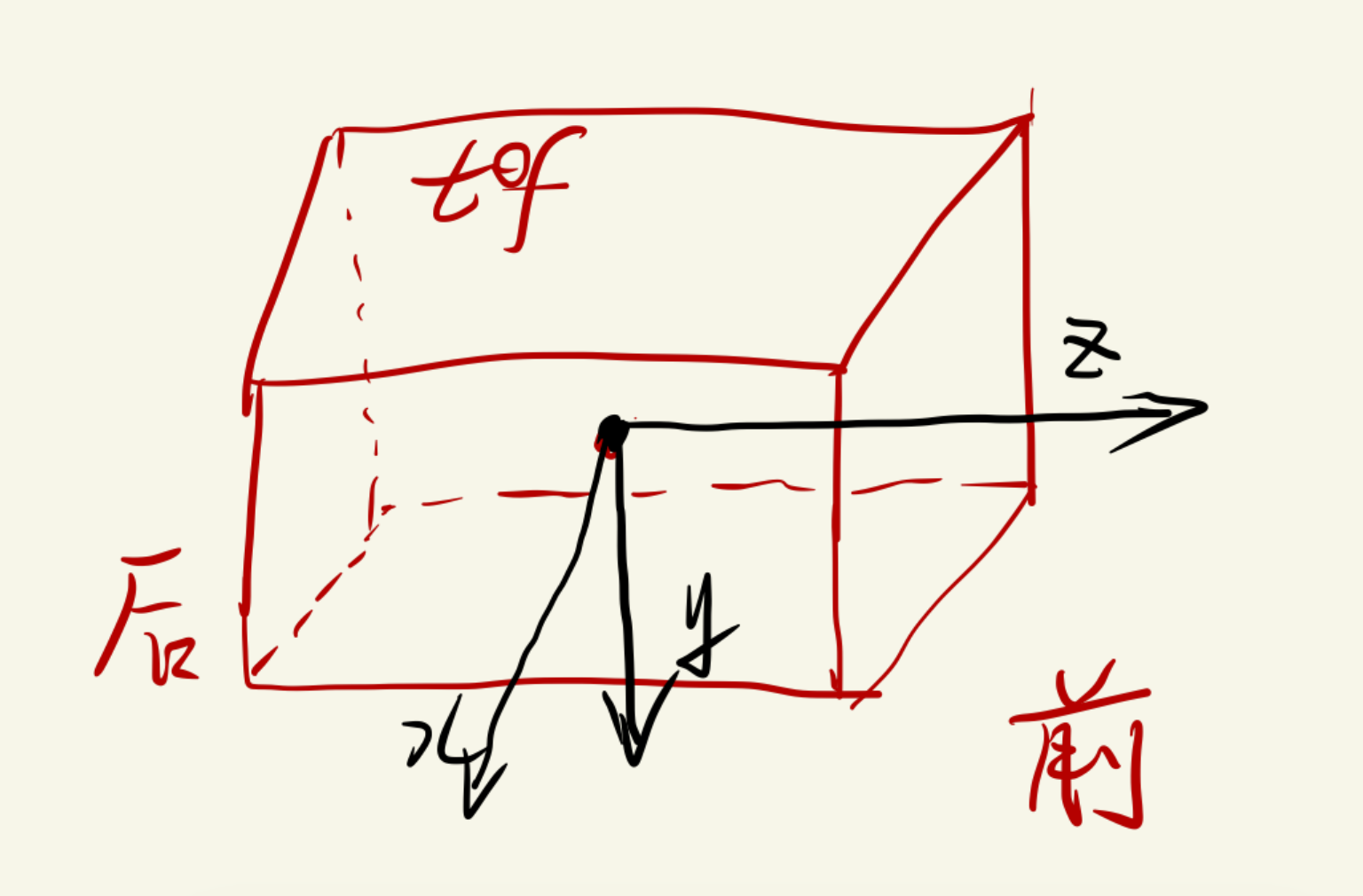
urdf文件给ROS2加载来生成tf关系用。意味着需要两个版本。一个版本,深度相机的坐标系按朝向为x轴,左侧为y轴,向上为z轴来设置。这个主要是为了转成sdf文件时给gazebo使用。另一个版本是,深度相机的坐标系设置成前z轴,右侧x轴,下为y轴。这个版本主要给ROS2加载来生成tf关系并可在rviz中显示车体模型。相机的坐标系:
正前方是
z轴右边为
x轴下边为
y轴 -
visual的模型和collision的模型最好分开导出来。collision的模型最好用最基础的形状。因为collision的模型需要尽量规则简单。在gazebo中激光传感器只能感知到collision模型。碰撞也只能感知collision模型。而collision模型只关注外壳的尺寸,这意味着内部多余的零件可以删掉,以减轻仿真的复杂性。当然对于不复杂的模型可以直接使用原来的模型,不必专门再画一个collision模型。
使用solidworks的sw_urdf_exporter插件导出模型
具体的操作步骤可以参考下面这篇文章:
https://mp.weixin.qq.com/s/Sg-11Lhdm7qUnOeCofGIaQ
2. 将生成的urdf文件头部替换掉
原来的为
<!-- This URDF was automatically created by SolidWorks to URDF Exporter! Originally created by Stephen Brawner ([email protected])
     Commit Version: 1.6.0-1-g15f4949  Build Version: 1.6.7594.29634
     For more information, please see <http://wiki.ros.org/sw_urdf_exporter> -->
<robot
  name="robot_model">
替换成
<robot name="robot_model"
  xmlns:xacro="http://ros.org/wiki/xacro">
3. 修改urdf文件来生成sdf文件
转换命令
gz sdf -p my_model.urdf > my_model.sdf
转换sdf文件时不要添加base_footprint。加了的话,会把固定的joint全部转换到base_footprint下面。而base_link会被删掉。所以转换后再添加。
将joint都改成continuous,这样的话用命令生成sdf文件时,每一个link都会单独出来,否则fixed的link会和base_link合在一起。
然后再将原来是fixed的joint的改回fixed类型。
转换后每个link里面都加了
<pose relative_to='caster_joint'>0 0 0 0 -0 0</pose>
把joint标签里的位置关系复制到link标签里。
	<link name='lidar_link'>
      <pose relative_to='right_lidar_joint'>0 0 0 0 -0 0</pose> #将joint中的pose信息剪切到这里
      <inertial>
        <pose>-0.000808 -0 -0.013363 0 -0 0</pose>
        <mass>0.174397</mass>
        <inertia>
          <ixx>8.9738e-05</ixx>
          <ixy>-1.68649e-20</ixy>
          <ixz>-2.47963e-06</ixz>
          <iyy>0.000104673</iyy>
          <iyz>-8.13365e-20</iyz>
          <izz>0.000113012</izz>
        </inertia>
      </inertial>
      <collision name='lidar_link_collision'>
        <pose>0 0 0 0 -0 0</pose>
        <geometry>
          <mesh>
            <scale>1 1 1</scale>
            <uri>model://lidar_link.STL</uri> #写明模型路径
          </mesh>
        </geometry>
      </collision>
      <visual name='right_lidar_link_visual'>
        <pose>0 0 0 0 -0 0</pose>
        <geometry>
          <mesh>
            <scale>1 1 1</scale>
            <uri>model://lidar_link.STL</uri> #写明模型路径
          </mesh>
        </geometry>
      </visual>
    </link>
4. vscode打开sdf文件,没有高亮显示的话,需要在文件开头加上
<?xml version="1.0" ?>
5. sdf文件的版本要设置为1.5
<sdf version='1.5'>
6. 有两种urdf文件
机器人车头朝向为x轴,左侧为y轴,向上为z轴。各个传感器零件也需要设置为这个坐标系。以这种坐标系生成的urdf文件转换的sdf文件是给gazebo用的。
将深度相机的坐标系设置成前z轴,右侧x轴,下为y轴。这个版本生成的urdf文件主要用于rviz加载显示和设定系统tf关系。
7. inertial 参数设置的不对。物体会在空中乱晃。
<inertial>
        <pose>-0.013558 -0.000602 -0.000258 0 -0 0</pose>
        <mass>0.03</mass>
        <inertia>
          <ixx>0.000031</ixx>
          <ixy>0</ixy>
          <ixz>0</ixz>
          <iyy>0.000013</iyy>
          <iyz>0</iyz>
          <izz>0.000031</izz>
        </inertia>
</inertial>
可以尝试使用下面的脚本计算简单形状的inertial 参数。
#!/usr/bin/env python3

import os

"""
该python代码是参考下面的计算方式写的
  <!-- Define intertial property macros  -->
  <xacro:macro name="box_inertia" params="m w h d">
    <inertial>
      <origin xyz="0 0 0" rpy="${pi/2} 0 ${pi/2}"/>
      <mass value="${m}"/>
      <inertia ixx="${(m/12) * (h*h + d*d)}" ixy="0.0" ixz="0.0" iyy="${(m/12) * (w*w + d*d)}" iyz="0.0" izz="${(m/12) * (w*w + h*h)}"/>
    </inertial>
  </xacro:macro>


  <xacro:macro name="cylinder_inertia" params="m r h">
    <inertial>
      <origin xyz="0 0 0" rpy="${pi/2} 0 0" />
      <mass value="${m}"/>
      <inertia ixx="${(m/12) * (3*r*r + h*h)}" ixy = "0" ixz = "0" iyy="${(m/12) * (3*r*r + h*h)}" iyz = "0" izz="${(m/2) * (r*r)}"/>
    </inertial>
  </xacro:macro>

  <xacro:macro name="sphere_inertia" params="m r">
    <inertial>
      <mass value="${m}"/>
      <inertia ixx="${(2/5) * m * (r*r)}" ixy="0.0" ixz="0.0" iyy="${(2/5) * m * (r*r)}" iyz="0.0" izz="${(2/5) * m * (r*r)}"/>
    </inertial>
  </xacro:macro>
"""

#m->mass 质量 unit: kg
#w->width  ->y方向
#d->length ->x方向
#h->height ->z方向
def box_inertia(m, w, h, d):
  """
  Callback function.
  """
  mass = m
  ixx = (m/12) * (h*h + d*d)
  ixy = 0.0
  ixz = 0.0
  iyy = (m/12) * (w*w + d*d)
  iyz = 0.0
  izz = (m/12) * (w*w + h*h)
  print('ixx=%f' % ixx)
  print('ixy=%f' % ixy)
  print('ixz=%f' % ixz)
  print('iyy=%f' % iyy)
  print('iyz=%f' % iyz)
  print('izz=%f' % izz)


#m->mass 质量
#r->cylinder radius
#h->cylinder height
def cylinder_inertia(m, r, h):
  """
  Callback function.
  """
  mass = m
  ixx = (m/12) * (3*r*r + h*h)
  ixy = 0.0
  ixz = 0.0
  iyy = (m/12) * (3*r*r + h*h)
  iyz = 0.0
  izz = (m/2) * (r*r)
  print('ixx=%f' % ixx)
  print('ixy=%f' % ixy)
  print('ixz=%f' % ixz)
  print('iyy=%f' % iyy)
  print('iyz=%f' % iyz)
  print('izz=%f' % izz)


#m->mass 质量
#r->sphere radius
def sphere_inertia(m, r):
  """
  Callback function.
  """
  mass = m
  ixx = (2/5) * m * (r*r)
  ixy = 0.0
  ixz = 0.0
  iyy = (2/5) * m * (r*r)
  iyz = 0.0
  izz = (2/5) * m * (r*r)
  print('ixx=%f' % ixx)
  print('ixy=%f' % ixy)
  print('ixz=%f' % ixz)
  print('iyy=%f' % iyy)
  print('iyz=%f' % iyz)
  print('izz=%f' % izz)


def main(args=None):
  box_inertia(0.051, 0.15, 0.03, 0.03)


if __name__ == '__main__':
  main()
8. 在sdf文件中添加超声波
ros2仿真中,超声波是用激光传感器来模拟的。
collision 标签中设置的大小会遮挡激光传感器的光束。对于小的传感器,其collision可以直接注释掉。以防止出现这种情况。
<link name='sonar_link'>
      <pose relative_to='base_link'>-0.221026 0.175662 0.145509 0 0 -3.14159</pose>
      <inertial>
        <pose>0 0 0 0 0 0</pose>
        <mass>0.03</mass>
        <inertia>
          <ixx>0.000031</ixx>
          <ixy>0</ixy>
          <ixz>0</ixz>
          <iyy>0.000013</iyy>
          <iyz>0</iyz>
          <izz>0.000031</izz>
        </inertia>
      </inertial>
      <!-- don't need to enable collision -->
      <!-- <collision name='sonar11_link_collision'>
        <pose>0 0 0 0 -0 0</pose>
        <geometry>
          <mesh>
            <scale>1 1 1</scale>
            <uri>model://sonar_link.STL</uri>
          </mesh>
          <box>
            <size>0.05 0.1 0.05</size>
          </box>
        </geometry>
      </collision> -->
      <visual name='sonar_link_visual'>
        <pose>0 0 0 0 -0 0</pose>
        <geometry>
          <mesh>
            <scale>1 1 1</scale>
            <uri>model://sonar_link.STL</uri>
          </mesh>
        </geometry>
      </visual>

      <sensor name="sonar_ultrasound" type="ray">
        <always_on>true</always_on>
        <visualize>true</visualize>
        <pose>0.0 0 0.0 0 0 0</pose>
        <update_rate>50</update_rate>
        <ray>
            <scan>
                <horizontal>
                    <samples>5</samples>
                    <resolution>1.0</resolution>
                    <min_angle>-0.18</min_angle>
                    <max_angle>0.18</max_angle>
                </horizontal>
                <vertical>
                    <samples>5</samples>
                    <resolution>1.0</resolution>
                    <min_angle>-0.01</min_angle>
                    <max_angle>0.01</max_angle>
                </vertical>
            </scan>
            <range>
                <min>0.02</min>
                <max>2</max>
                <resolution>0.01</resolution>
            </range>
            <noise>
                <type>gaussian</type>
                <mean>0.0</mean>
                <stddev>0.01</stddev>
            </noise>
        </ray>
        <plugin name="sonar_bytes_ultrasound" filename="libgazebo_ros_ray_sensor.so">
            <ros>
                <!-- <namespace>distance</namespace> -->
                <remapping>~/out:=sonar</remapping>
            </ros>
            <output_type>sensor_msgs/Range</output_type>
            <radiation_type>ultrasound</radiation_type>
            <frame_name>sonar_link</frame_name>
        </plugin>
    </sensor>
    <material>Gazebo/Blue</material>
    </link>
9. 在sdf文件中添加lidar
<link name='lidar_link'>
      <pose relative_to='base_link'>0.69731 0.23521 0.20928 0 -0 0</pose>
      <inertial>
        <pose>-0.000808 0 -0.013363 0 -0 0</pose>
        <mass>0.174397</mass>
        <inertia>
          <ixx>8.9738e-05</ixx>
          <ixy>-2.53841e-20</ixy>
          <ixz>-2.47963e-06</ixz>
          <iyy>0.000104673</iyy>
          <iyz>-8.06184e-20</iyz>
          <izz>0.000113012</izz>
        </inertia>
      </inertial>
      <collision name='lidar_link_collision'>
        <pose>0 0 0 0 -0 0</pose>
        <geometry>
          <!-- <cylinder>
            <radius>0.029</radius>
            <length>0.0325</length>
          </cylinder> -->
          <mesh>
            <scale>1 1 1</scale>
            <uri>model://lidar_link.STL</uri>
          </mesh>
        </geometry>
      </collision>
      <visual name='left_lidar_link_visual'>
        <pose>0 0 0 0 -0 0</pose>
        <geometry>
          <mesh>
            <scale>1 1 1</scale>
            <uri>model://lidar_link.STL</uri>
          </mesh>
        </geometry>
      </visual>
      <sensor name="hls_lfcd_lds" type="ray">
        <always_on>true</always_on>
        <visualize>true</visualize>
        <pose>0 0 0 0 0 0</pose>
        <update_rate>15</update_rate>
        <ray>
          <scan>
            <horizontal>
              <samples>960</samples>
              <resolution>1.0</resolution>
              <min_angle>-3.14</min_angle>
              <max_angle>3.14</max_angle>
            </horizontal>
          </scan>
          <range>
            <min>0.10000</min>
            <max>30.0</max>
            <resolution>0.015000</resolution>
          </range>
          <noise>
            <type>gaussian</type>
            <mean>0.0</mean>
            <stddev>0.01</stddev>
          </noise>
        </ray>
        <plugin name="robot_laserscan" filename="libgazebo_ros_ray_sensor.so">
          <ros>
            <!-- <namespace>/tb3</namespace> -->
            <remapping>~/out:=scan</remapping>
          </ros>
          <output_type>sensor_msgs/LaserScan</output_type>
          <frame_name>lidar_link</frame_name>
        </plugin>
      </sensor>

    </link>
<remapping>~/out:=scan</remapping> 映射话题名称的标签。右边是自己定义的标签。
horizontal标签中的resolution并没有发挥作用。samples参数决定了设定角度里有多少采样点,同时决定了后面发出的scan话题有多少个数据。
为了便于理解,把gazebo中读取标签属性值的代码放在这里。
void MultiRayShape::Init()
{
  ignition::math::Vector3d start, end, axis;
  double yawAngle, pitchAngle;
  ignition::math::Quaterniond ray;
  double yDiff;
  double horzMinAngle, horzMaxAngle;
  int horzSamples = 1;
  // double horzResolution = 1.0;

  double pDiff = 0;
  int vertSamples = 1;
  // double vertResolution = 1.0;
  double vertMinAngle = 0;

  this->rayElem = this->sdf->GetElement("ray");
  this->scanElem = this->rayElem->GetElement("scan");
  this->horzElem = this->scanElem->GetElement("horizontal");
  this->rangeElem = this->rayElem->GetElement("range");

  if (this->scanElem->HasElement("vertical"))
  {
    this->vertElem = this->scanElem->GetElement("vertical");
    vertMinAngle = this->vertElem->Get<double>("min_angle");
    double vertMaxAngle = this->vertElem->Get<double>("max_angle");
    vertSamples = this->vertElem->Get<unsigned int>("samples");
    // vertResolution = this->vertElem->Get<double>("resolution");
    pDiff = vertMaxAngle - vertMinAngle;
  }

  horzMinAngle = this->horzElem->Get<double>("min_angle");
  horzMaxAngle = this->horzElem->Get<double>("max_angle");
  horzSamples = this->horzElem->Get<unsigned int>("samples");
  // horzResolution = this->horzElem->Get<double>("resolution");
  yDiff = horzMaxAngle - horzMinAngle;

  this->minRange = this->rangeElem->Get<double>("min");
  this->maxRange = this->rangeElem->Get<double>("max");

  this->offset = this->collisionParent->RelativePose();

  // Create an array of ray collisions
  for (unsigned int j = 0; j < (unsigned int)vertSamples; ++j)
  {
    for (unsigned int i = 0; i < (unsigned int)horzSamples; ++i)
    {
      yawAngle = (horzSamples == 1) ? 0 :
        i * yDiff / (horzSamples - 1) + horzMinAngle;

      pitchAngle = (vertSamples == 1)? 0 :
        j * pDiff / (vertSamples - 1) + vertMinAngle;

      // since we're rotating a unit x vector, a pitch rotation will now be
      // around the negative y axis
      ray.Euler(ignition::math::Vector3d(0.0, -pitchAngle, yawAngle));
      axis = this->offset.Rot() * ray * ignition::math::Vector3d::UnitX;

      start = (axis * this->minRange) + this->offset.Pos();
      end = (axis * this->maxRange) + this->offset.Pos();

      this->AddRay(start, end);
    }
  }
}
10. 在sdf文件中添加深度相机
<link name='camera_link'>
      <pose relative_to='base_link'> 0.7225 0 0.87858 0 -0 0</pose>
      <self_collide>0</self_collide>
      <inertial>
        <pose>0 0 0 0 -0 0</pose>
        <mass>0.114</mass>
        <inertia>
          <ixx>0.001</ixx>
          <ixy>0.000</ixy>
          <ixz>0.000</ixz>
          <iyy>0.001</iyy>
          <iyz>0.000</iyz>
          <izz>0.001</izz>
        </inertia>
      </inertial>
      <!-- don't need to enable collision -->
      <!-- <collision name='front_tof_link_collision'>
        <pose>0 0 0 0 -0 0</pose>
        <geometry>
          <mesh>
            <scale>1 1 1</scale>
            <uri>model://camera_link.STL</uri>
          </mesh>
          <box>
            <size>0.15 0.03 0.03</size>
          </box>
          <box>
            <size>0.03 0.03 0.03</size>
          </box>
        </geometry>
      </collision> -->
      <visual name='camera_link_visual'>
        <pose>0 0 0 0 -0 0</pose>
        <geometry>
          <mesh>
            <scale>1 1 1</scale>
            <uri>model://camera_link.STL</uri>
          </mesh>
        </geometry>
      </visual>

      <sensor name="camera_depth" type="depth">
        <always_on>true</always_on>
        <update_rate>15</update_rate>
        <visualize>true</visualize>
        <pose>0 0 0 0 0 0</pose>
        <camera name="realsense_depth_camera">
            <horizontal_fov>1.46608</horizontal_fov>
            <image>
                <width>424</width>
                <height>240</height>
                <format>B8G8R8</format>
            </image>
            <clip>
                <near>0.05</near>
                <far>8</far>
            </clip>
        </camera>
        <plugin name="realsense_d430_depth_driver" filename="libgazebo_ros_camera.so">
            <ros>
                <!-- <namespace>d430</namespace> -->
                <!-- <remapping>front_tof/image_raw:=color/image_raw</remapping>
                <remapping>front_tof/depth/image_raw:=depth/image_rect_raw</remapping>
                <remapping>front_tof/camera_info:=camera_info</remapping>
                <remapping>front_tof/depth/camera_info:=depth/camera_info</remapping>
                <remapping>front_tof/points:=depth/points</remapping> -->
            </ros>
            <camera_name>camera</camera_name>
            <frame_name>camera_link</frame_name>
            <hack_baseline>0.07</hack_baseline>
            <min_depth>0.05</min_depth>
            <max_depth>8.0</max_depth>
        </plugin>
      </sensor>
    </link>
libgazebo_ros_camera.so 插件发布的话题会自动加上插件中camera_name标签的名字,可以不用再重映射名字。
11. 在sdf文件中增加单目摄像头
<link name='front_camera_link'>
      <pose relative_to='base_link'>0.730409 -0.000138 0.81771 0 -0 0</pose>
      <inertial>
        <pose>0 0 0 0 -0 0</pose>
        <mass>0.114</mass>
        <inertia>
          <ixx>0.001</ixx>
          <ixy>0.000</ixy>
          <ixz>0.000</ixz>
          <iyy>0.001</iyy>
          <iyz>0.000</iyz>
          <izz>0.001</izz>
        </inertia>
      </inertial>
      <!-- <collision name='front_camera_link_collision'>
        <pose>0 0 0 0 -0 0</pose>
        <geometry>
          <mesh>
            <scale>1 1 1</scale>
            <uri>model://front_camera_link.STL</uri>
          </mesh>
        </geometry>
      </collision> -->
      <visual name='front_camera_link_visual'>
        <pose>0 0 0 0 -0 0</pose>
        <geometry>
          <mesh>
            <scale>1 1 1</scale>
            <uri>model://front_camera_link.STL</uri>
          </mesh>
        </geometry>
      </visual>

      <sensor type="camera" name="front_camera">
        <always_on>true</always_on>
        <visualize>false</visualize>
        <update_rate>15.0</update_rate>
        <camera name="front_camera">
            <horizontal_fov>1.46608</horizontal_fov>
            <image>
                <width>320</width>
                <height>180</height>
                <format>R8G8B8</format>
            </image>
            <distortion>
                <k1>0.0</k1>
                <k2>0.0</k2>
                <k3>0.0</k3>
                <p1>0.0</p1>
                <p2>0.0</p2>
                <center>0.5 0.5</center>
            </distortion>
        </camera>
        <plugin name="front_camera_plugin_name" filename="libgazebo_ros_camera.so">
            <ros>
                <!-- <namespace>stereo</namespace> -->
                <!-- <remapping>front_tof_camera/image_raw:=image_raw</remapping>
                <remapping>front_tof_camera/camera_info:=camera_info</remapping> -->
            </ros>
            <!-- Set camera name. If empty, defaults to sensor name (i.e. "sensor_name") -->
            <camera_name>front_camera</camera_name>
            <!-- Set TF frame name. If empty, defaults to link name (i.e. "link_name") -->
            <frame_name>front_camera_link</frame_name>
            <hack_baseline>0.2</hack_baseline>
        </plugin>
      </sensor>
      <material>Gazebo/Green</material>
    </link>
libgazebo_ros_camera.so 插件发布的话题会自动加上插件中camera_name标签的名字,可以不用再重映射名字。
针对libgazebo_ros_camera.so 插件,gazebo需要的sdf文件,深度相机的坐标系均以前为x轴,左侧为y轴,上为z轴。但是ROS2加载的urdf文件需按照相机的坐标系来写,以便确定正确的TF转换关系。即前为z轴,右侧为x轴,下为y轴。
libgazebo_ros_camera 插件中frame_name 标签会作为发布话题的frame_id。
header:
  stamp:
    sec: 149
    nanosec: 506000000
  frame_id: front_tof_link
height: 1
width: 101760
12. 启动Rviz2导入机器人模型。使用gui可以查看各个link设置的是否正确。
安装joint_state_publisher_gui
sudo apt install ros-galactic-joint_state_publisher_gui
ros2 launch two_wheeled_robot two_wheeled_robot_rviz.launch.py gui:=True
需要注意的是,continuous类型的joint必须设置好axis标签。否则导入时会显示不出来。如下:
<joint
    name="right_wheel_joint"
    type="continuous">
    <origin
      xyz="-0.000117203739848026 -0.242033768708315 -0.000508908915354045"
      rpy="0 0 0" />
    <parent
      link="base_link" />
    <child
      link="right_wheel_link" />
    <axis
      xyz="0 1 0" />   #哪个轴旋转就在哪个轴上置1
  </joint>
13. 在gazebo中加载一个机器人模型
1)确保模型处于环境变量所在的目录下
首先,我们要将模型所在的文件夹(其中包含一个sdf模型文件和一个config配置文件)放到gazebo环境变量所在的目录下,例如下面的默认目录:
~/.gazebo/models
当然,也可以在~/.bashrc文件中添加更多gazebo模型所在路径的环境变量:
export GAZEBO_MODEL_PATH="${HOME}/wpilib/simulation/models:${GAZEBO_MODEL_PATH}"
#${HOME}/wpilib/simulation/models为示例路径,应根据自己的实际情况改成自己的。
或者在launch文件中写明GAZEBO_MODEL_PATH的路径。
os.environ["GAZEBO_MODEL_PATH"] = “path/to/gazebo_models”
2)添加机器人模型
-
直接在
world文件中包含需要的模型。 -
通过
robot_description话题来添加。在launch文件中使用robot_state_publisher节点读取urdf文件,发布robot_description话题。然后用spawn_entity.py脚本接收robot_description话题来生成一个机器人模型。
# Subscribe to the joint states of the robot, and publish the 3D pose of each link.
  start_robot_state_publisher_cmd = Node(
    package='robot_state_publisher',
    executable='robot_state_publisher',
    parameters=[{'robot_description': Command(['xacro ', urdf_model])}])

  # Publish the joint states of the robot
  start_joint_state_publisher_cmd = Node(
    package='joint_state_publisher',
    executable='joint_state_publisher',
    name='joint_state_publisher',
    condition=UnlessCondition(gui))

# Launch the robot
  spawn_entity_cmd = Node(
    package='gazebo_ros',
    executable='spawn_entity.py',
    arguments=['-entity', robot_name_in_model,
                '-topic', 'robot_description',
                    '-x', spawn_x_val,
                    '-y', spawn_y_val,
                    '-z', spawn_z_val,
                    '-Y', spawn_yaw_val],
                    output='screen')
- 直接读取
sdf文件中描述的机器人模型。前面转换sdf文件就是为了能在这里加载。
start_gazebo_ros_spawner_cmd = Node(
        package='gazebo_ros',
        executable='spawn_entity.py',
        arguments=[
            '-entity', ROBOT_MODEL,
            '-file', sdf_path,  #sdf_path为模型文件的路径
            '-x', x_pose,
            '-y', y_pose,
            '-z', z_pose,
            '-Y', theta
           ],
        output='screen',
    )
总结
上面介绍的东西有点多显的有点乱。这里总结一下制作gazebo机器人模型的流程思路。
- 使用
solidworks整理一下机器人模型。主要是精简模型,保证一个link只对应一个零件。机器人内部的零件可以删掉以便减少复杂度。 - 使用
solidworks中的sw_urdf_exporter插件导出机器人模型的urdf文件。 - 修改导出的
urdf文件,然后转换成sdf文件。 - 在
sdf文件中添加gazebo传感器和执行器插件。
参考
https://automaticaddison.com/how-to-load-a-robot-model-sdf-format-into-gazebo-ros-2/
https://automaticaddison.com/how-to-load-a-urdf-file-into-gazebo-ros-2/
觉得有用就点赞吧!
我是首飞,一个帮大家填坑的机器人开发攻城狮。
另外在公众号《首飞》内回复“机器人”获取精心推荐的C/C++,Python,Docker,Qt,ROS1/2等机器人行业常用技术资料。
