目录
22. Q5a: Serial two's complementer (Moore FSM)
23. Q5b: Serial two's complementer (Mealy FSM)
28. Q6c: FSM one-hot next-state logic
31. Q2b: One-hot FSM equations
3.2 Sequential Logic
3.2.5 Finite State Machines
21. Q8: Design a Mealy FSM
Implement a Mealy-type finite state machine that recognizes the sequence "101" on an input signal named x. Your FSM should have an output signal, z, that is asserted to logic-1 when the "101" sequence is detected. Your FSM should also have an active-low asynchronous reset. You may only have 3 states in your state machine. Your FSM should recognize overlapping sequences.
mealy 状态机,输出不仅与当前状态有关,还与输入信号有关。
module top_module (
    input clk,
    input aresetn,    // Asynchronous active-low reset
    input x,
    output z );

    parameter IDLE=0,S0=1,S1=2;
    reg [1:0] state,next_state;

    always @(*)begin
        case(state)
            IDLE:begin
                next_state=x?S0:IDLE;
            end
            S0:begin
                next_state=x?S0:S1;
            end
            S1:begin
                next_state=x?S0:IDLE;
            end
            default:begin
                next_state<=IDLE;
            end
        endcase
    end

    always @(posedge clk or negedge aresetn)begin
        if(aresetn==1'b0)begin
            state<=IDLE;
        end
        else begin
            state<=next_state;
        end
    end

    assign z=(state==S1)&& x==1'b1;

endmodule
22. Q5a: Serial two's complementer (Moore FSM)
You are to design a one-input one-output serial 2's complementer Moore state machine. The input (x) is a series of bits (one per clock cycle) beginning with the least-significant bit of the number, and the output (Z) is the 2's complement of the input. The machine will accept input numbers of arbitrary length. The circuit requires an asynchronous reset. The conversion begins when Reset is released and stops when Reset is asserted.
For example:
module top_module (
    input clk,
    input areset,
    input x,
    output z
);

    parameter  idle = 2'b00,s0   = 2'b01, s1   = 2'b10;

    reg [1:0]   state;
    reg [1:0]   next_state;


    always@(*)begin
        next_state = idle;
        case(state)
            idle:next_state = x? s0:idle;
            s0  : next_state = s1;
            s1  : next_state = s1;
            default:next_state = idle;
        endcase
    end

     always@(posedge clk or posedge areset)begin
        if(areset)
            state <= idle;
        else
            state <= next_state;
    end

    always@(posedge clk or posedge areset)begin
        if(areset)
            z <= 1'b0;
        else
            case(next_state)
                idle:z <= 1'b0;
                s0  : z <= 1'b1;
                s1  : z <= ~x;
            endcase
    end


endmodule
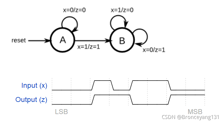
23. Q5b: Serial two's complementer (Mealy FSM)
The following diagram is a Mealy machine implementation of the 2's complementer. Implement using one-hot encoding.
module top_module (
    input clk,
    input areset,
    input x,
    output z
);
   parameter s0=0,s1=1;
   reg state,next_state;

    always @(*)begin
        case(state)
            s0: next_state=x?s1:s0;
            s1: next_state=s1;
            default: next_state=s0;
        endcase
    end
    always @(posedge clk or posedge areset)begin
        if(areset) state<=s0;
        else state<=next_state;
    end

    assign z=(state==s0 && x==1'b1) |(state==s1 && x==1'b0);

endmodule
24. Q3a: FSM
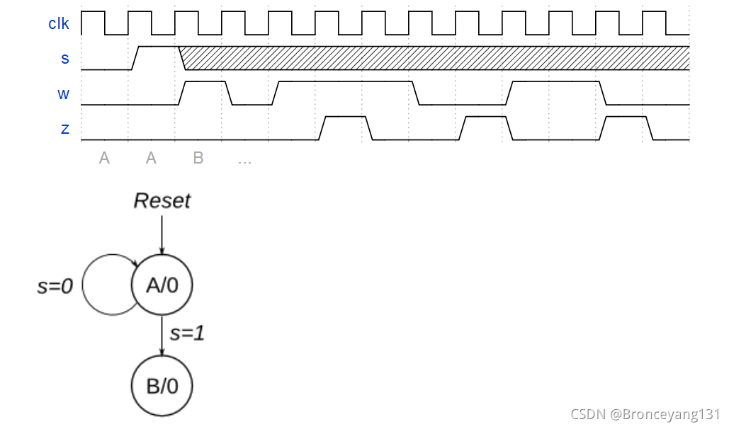
Consider a finite state machine with inputs s and w. Assume that the FSM begins in a reset state called A, as depicted below. The FSM remains in state Aas long as s = 0, and it moves to state B when s = 1. Once in state B the FSM examines the value of the input w in the next three clock cycles. If w = 1 in exactly two of these clock cycles, then the FSM has to set an output z to 1 in the following clock cycle. Otherwise z has to be 0. The FSM continues checking w for the next three clock cycles, and so on. The timing diagram below illustrates the required values of z for different values of w.
Use as few states as possible. Note that the s input is used only in state A, so you need to consider just the w input.
module top_module (
    input clk,
    input reset,   // Synchronous reset
    input s,
    input w,
    output z
);


    parameter A=0,B=1;
    reg state,next_state;
    reg [1:0] bit1_counter;
    reg [1:0] w_counter;

    always @(*)begin
        case(state)
            A: begin
                next_state=s?B:A;
            end
            B:begin
                next_state=B;
            end
            default:begin
                next_state=A;
            end
        endcase
    end
    always @(posedge clk )begin
        if(reset) begin
                state<=A;
        end
       else begin
           state<=next_state;
       end
    end

    //
    always @(posedge clk)begin
        if(reset)
            w_counter <= 0;
    else if(w_counter == 2'd2)
        w_counter <= 0;
    else if(state == B)
        w_counter <= w_counter + 1;
    end

    always @(posedge clk)begin
        if(reset)
            bit1_counter <= 0;
    else if(w_counter == 2'd0 && w == 0)
        bit1_counter <= 0;
    else if(w_counter == 2'd0 && w==1)
        bit1_counter <= 1;
    else if(w == 1 && state == B)
        bit1_counter <= bit1_counter + 1;
    end

    assign z = (state == B && bit1_counter == 2 && w_counter == 0);


endmodule
25. Q3b: FSM
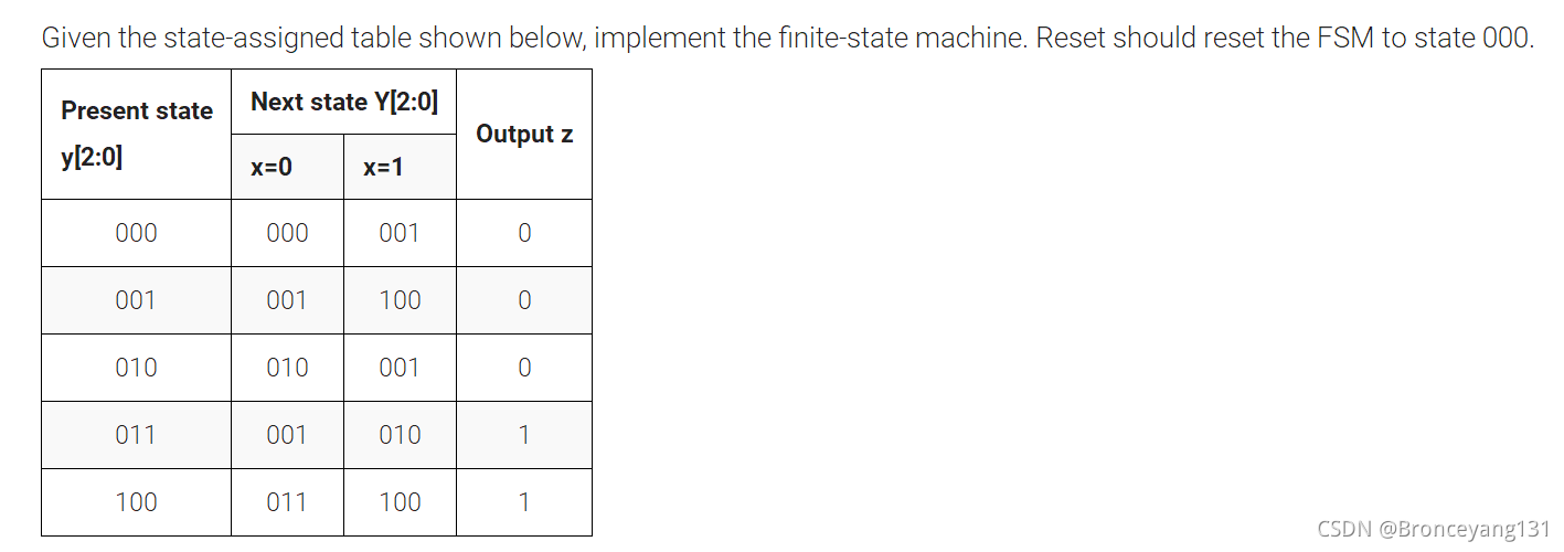
module top_module (
    input clk,
    input reset,   // Synchronous reset
    input x,
    output z
);
    parameter S0=0,S1=1,S2=2,S3=3,S4=4;
    reg [2:0] state,next_state;

    always @(*)begin
        case (state)
            S0:begin
                if(x==1'b1) next_state=S1;
                else  next_state=S0;
            end
            S1:begin
                if(x==1'b1) next_state=S4;
                else  next_state=S1;
            end
            S2:begin
                if(x==1'b1) next_state=S1;
                else  next_state=S2;
            end
            S3:begin
                if(x==1'b1) next_state=S2;
                else  next_state=S1;
            end
             S4:begin
                 if(x==1'b1) next_state=S4;
                else  next_state=S3;
            end
            default:next_state=S0;
        endcase
    end
    always @(posedge clk)begin
        if(reset) state<=S0;
        else state<=next_state;
    end
    assign z=(state==S3 | state==S4);

endmodule26. Q3c: FSM logic
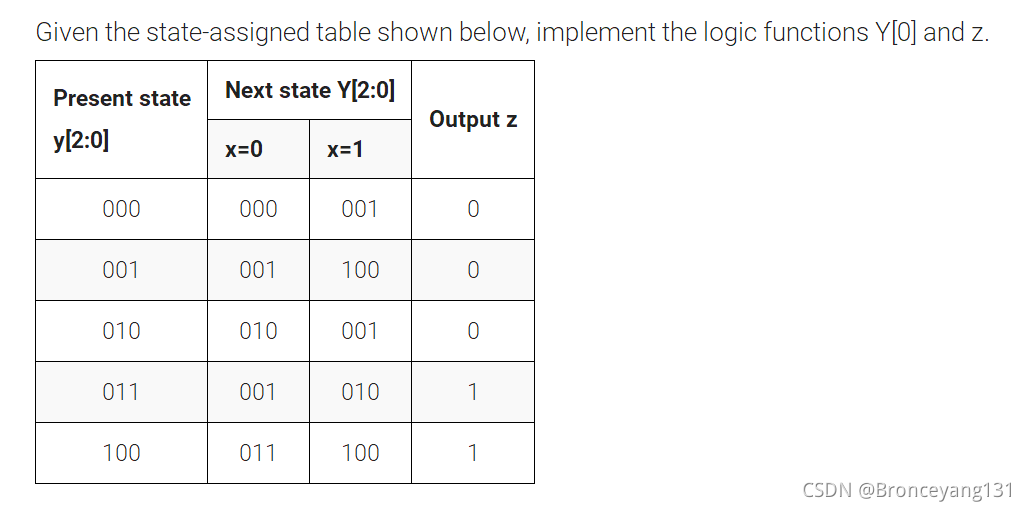
module top_module (
    input clk,
    input [2:0] y,
    input x,
    output Y0,
    output z
);
    parameter S0=3'b000,S1=3'b001,S2=3'b010,S3=3'b011,S4=3'b100;
    reg [2:0] state,next_state;

    always@(*)begin
        case(y)
            S0:next_state=x?S1:S0;
            S1:next_state=x?S4:S1;
            S2:next_state=x?S1:S2;
            S3:next_state=x?S2:S1;
            S4:next_state=x?S4:S3;
            default:next_state=S0;
        endcase
    end

    assign z=y==S3||y==S4;
    assign Y0=next_state[0];

endmodule
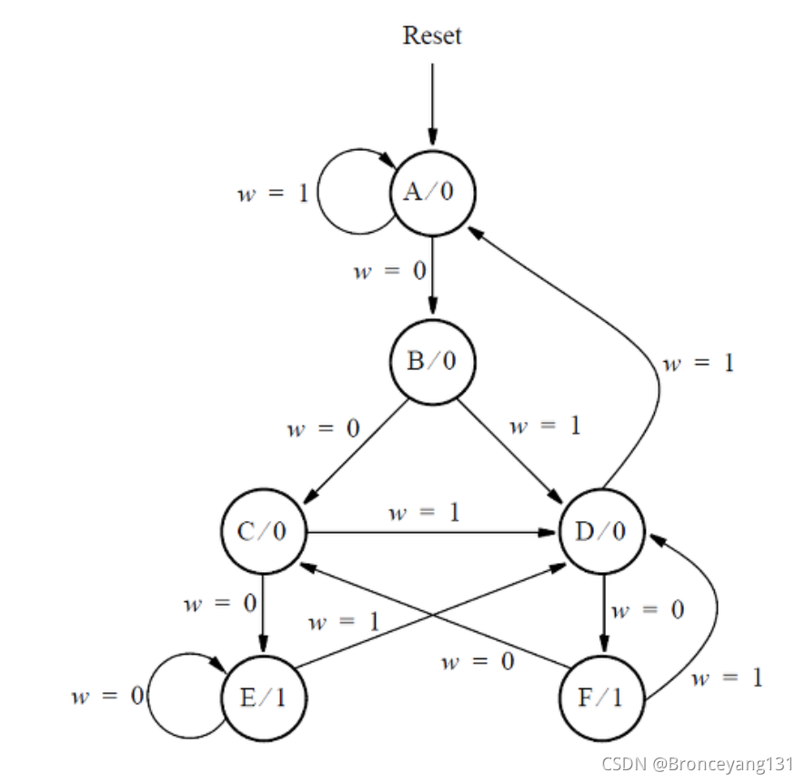
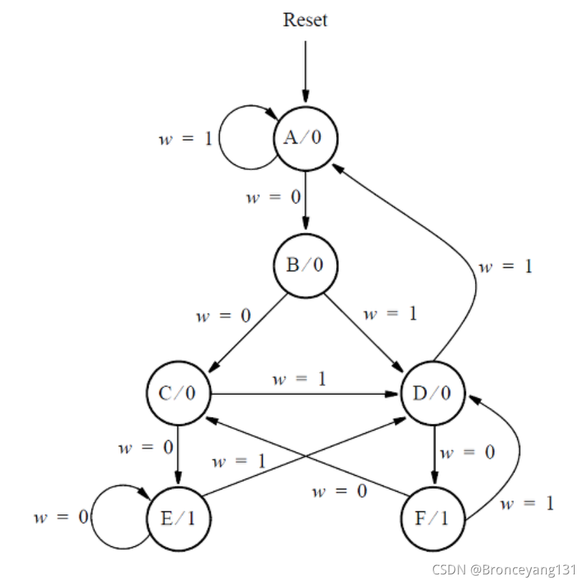
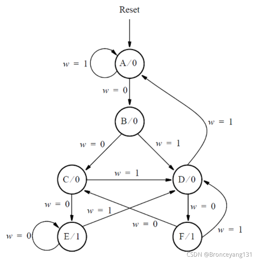
27. Q6b: FSM next-state logic
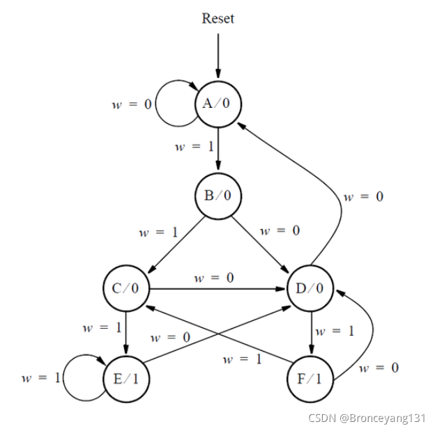
Assume that you wish to implement the FSM using three flip-flops and state codes y[3:1] = 000, 001, ... , 101 for states A, B, ... , F, respectively. Show a state-assigned table for this FSM. Derive a next-state expression for the flip-flop y[2].
Implement just the next-state logic for y[2]. (This is much more a FSM question than a Verilog coding question. Oh well.)
module top_module (
    input [3:1] y,
    input w,
    output Y2);
    parameter A=3'b000,B=3'b001,C=3'b010,D=3'b011,E=3'b100,F=3'b101;
    reg [2:0] next_state;

    always @(*)begin
        case(y)
            A:begin
                if(w)next_state=A;
                else next_state=B;
            end
             B:begin
                 if(w)next_state=D;
                else next_state=C;
            end
             C:begin
                 if(w)next_state=D;
                else next_state=E;
            end
             D:begin
                if(w)next_state=A;
                else next_state=F;
            end
             E:begin
                 if(w)next_state=D;
                else next_state=E;
            end
             F:begin
                 if(w)next_state=D;
                else next_state=C;
            end
            default:next_state=A;
        endcase
    end

    assign Y2=next_state[1];


endmodule
28. Q6c: FSM one-hot next-state logic
For this part, assume that a one-hot code is used with the state assignment 'y[6:1] = 000001, 000010, 000100, 001000, 010000, 100000 for states A, B,..., F, respectively.
Write a logic expression for the next-state signals Y2 and Y4. (Derive the logic equations by inspection assuming a one-hot encoding. The testbench will test with non-one hot inputs to make sure you're not trying to do something more complicated).
根据next_state状态的由来进行反推。
module top_module (
    input [6:1] y,
    input w,
    output Y2,
    output Y4);
     parameter A=6'b000001,B=6'b000010,C=6'b000100,D=6'b001000;
    parameter E=6'b010000,F=6'b100000;
    reg [6:1] next_state;

    always @(*)begin
        next_state[1]<=w?y[1]|y[4]:1'b0;
        next_state[2]<=w?1'b0:y[1];
        next_state[3]<=w?1'b0:y[2]|y[6];
        next_state[4]<=w?y[2]|y[3]|y[5]|y[6]:1'b0;
        next_state[5]<=w?1'b0:y[3]|y[5];
        next_state[6]<=w?1'b0:y[4];
    end

    assign Y2=next_state[2];
    assign Y4=next_state[4];


endmodule29. Q6: FSM
module top_module (
    input clk,
    input reset,     // synchronous reset
    input w,
    output z);
    parameter A=3'b000,B=3'b001,C=3'b010,D=3'b011,E=3'b100,F=3'b101;
    reg [2:0] state,next_state;

    always @(*)begin
        case(state)
            A:begin
                if(w)next_state=A;
                else next_state=B;
            end
             B:begin
                 if(w)next_state=D;
                else next_state=C;
            end
             C:begin
                 if(w)next_state=D;
                else next_state=E;
            end
             D:begin
                if(w)next_state=A;
                else next_state=F;
            end
             E:begin
                 if(w)next_state=D;
                else next_state=E;
            end
             F:begin
                 if(w)next_state=D;
                else next_state=C;
            end
            default:next_state=A;
        endcase
    end

    always@(posedge clk)begin
        if(reset) state<=A;
        else state<=next_state;
    end

    assign z=state==E|state==F;

endmodule
module top_module (
    input clk,
    input reset,   // Synchronous active-high reset
    input w,
    output z
);
 parameter A=3'b000,B=3'b001,C=3'b010,D=3'b011,E=3'b100,F=3'b101;
    reg [2:0] state,next_state;

    always @(*)begin
        case(state)
            A:begin
                if(w)next_state=B;
                else next_state=A;
            end
             B:begin
                 if(w)next_state=C;
                else next_state=D;
            end
             C:begin
                 if(w)next_state=E;
                else next_state=D;
            end
             D:begin
                 if(w)next_state=F;
                else next_state=A;
            end
             E:begin
                 if(w)next_state=E;
                else next_state=D;
            end
             F:begin
                 if(w)next_state=C;
                else next_state=D;
            end
            default:next_state=A;
        endcase
    end

    always@(posedge clk)begin
        if(reset) state<=A;
        else state<=next_state;
    end

    assign z=state==E|state==F;
endmodule
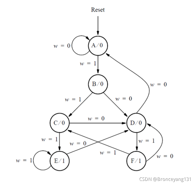
31. Q2b: One-hot FSM equations
Assume that a one-hot code is used with the state assignment y[5:0] = 000001(A), 000010(B), 000100(C), 001000(D), 010000(E), 100000(F)
Write a logic expression for the signal Y1, which is the input of state flip-flop y[1].
Write a logic expression for the signal Y3, which is the input of state flip-flop y[3].
(Derive the logic equations by inspection assuming a one-hot encoding. The testbench will test with non-one hot inputs to make sure you're not trying to do something more complicated).
module top_module (
    input [5:0] y,
    input w,
    output Y1,
    output Y3
);
   parameter A=6'b000001,B=6'b000010,C=6'b000100,D=6'b001000,
                    E=6'b010000,F=6'b100000;
    reg [5:0] next_state;

    always @(*)begin
        next_state[0]<=~w?y[0]|y[3]:1'b0;
        next_state[1]<=~w?1'b0:y[0];
        next_state[2]<=~w?1'b0:y[1]|y[5];
        next_state[3]<=~w?y[1]|y[2]|y[4]|y[5]:1'b0;
        next_state[4]<=~w?1'b0:y[2]|y[4];
        next_state[5]<=~w?1'b0:y[3];
    end

    assign Y1=next_state[1];
    assign Y3=next_state[3];

endmodule
32. Q2a: FSM
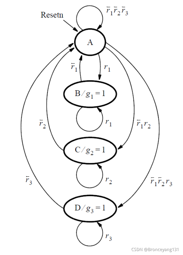
This FSM acts as an arbiter circuit, which controls access to some type of resource by three requesting devices. Each device makes its request for the resource by setting a signal r[i] = 1, where r[i] is either r[1], r[2], or r[3]. Each r[i] is an input signal to the FSM, and represents one of the three devices. The FSM stays in state A as long as there are no requests. When one or more request occurs, then the FSM decides which device receives a grant to use the resource and changes to a state that sets that device’s g[i] signal to 1. Each g[i] is an output from the FSM. There is a priority system, in that device 1 has a higher priority than device 2, and device 3 has the lowest priority. Hence, for example, device 3 will only receive a grant if it is the only device making a request when the FSM is in state A. Once a device, i, is given a grant by the FSM, that device continues to receive the grant as long as its request, r[i] = 1.
Write complete Verilog code that represents this FSM. Use separate always blocks for the state table and the state flip-flops, as done in lectures. Describe the FSM outputs, g[i], using either continuous assignment statement(s) or an always block (at your discretion). Assign any state codes that you wish to use.
考虑状态转移条件的优先级。
module top_module (
    input clk,
    input resetn,    // active-low synchronous reset
    input [3:1] r,   // request
    output [3:1] g   // grant
);
    parameter S0=2'b00,S1=2'b01,S2=2'b10,S3=2'b11;
    reg [1:0] state,next_state;

    always @(*)begin
        case(state)
            S0:begin
                if(r[1]) next_state=S1;
                else begin
                        if (~r[1]&&r[2])next_state=S2;
                        else begin
                            if(~r[1]&&~r[2]&&r[3])next_state=S3;
                            else next_state=S0;
                        end
                end
            end
            S1:begin
                if(r[1]) next_state=S1;
                else  next_state=S0;
            end
            S2:begin
                if(r[2]) next_state=S2;
                else  next_state=S0;
            end
            S3:begin
                if(r[3]) next_state=S3;
                else  next_state=S0;
            end
            default: next_state=S0;
        endcase
    end

    always @(posedge clk)begin
        if(~resetn) state<=S0;
        else state<=next_state;
    end

    assign g[1]=(state==S1);
    assign g[2]=(state==S2);
    assign g[3]=(state==S3);


endmodule
33. Q2b: Another FSM
consider a finite state machine that is used to control some type of motor. The FSM has inputs x and y, which come from the motor, and produces outputs f and g, which control the motor. There is also a clock input called clk and a reset input called resetn.
The FSM has to work as follows. As long as the reset input is asserted, the FSM stays in a beginning state, called state A. When the reset signal is de-asserted, then after the next clock edge the FSM has to set the output f to 1 for one clock cycle. Then, the FSM has to monitor the x input. When x has produced the values 1, 0, 1 in three successive clock cycles, then g should be set to 1 on the following clock cycle. While maintaining g = 1 the FSM has to monitor the y input. If y has the value 1 within at most two clock cycles, then the FSM should maintain g = 1 permanently (that is, until reset). But if y does not become 1 within two clock cycles, then the FSM should set g = 0 permanently (until reset).
(The original exam question asked for a state diagram only. But here, implement the FSM.)
module top_module (
    input clk,
    input resetn,    // active-low synchronous reset
    input x,
    input y,
    output f,
    output g
);
    parameter A=0,B=1,B1=2,B2=3,B3=4,C=5,C1=6,ONE=7,ZERO=8;
    reg [3:0]state,next_state;

    always @(*)begin
        case(state)
            A:begin
                next_state=B;
            end
            B:begin
                next_state=B1;
            end
            B1:begin
                if(x) next_state=B2;
                else next_state=B1;
            end
            B2:begin
                if(x) next_state=B2;
                else next_state=B3;
            end
            B3:begin
                if(x)next_state=C;
                else next_state=B1;
            end
            C:begin
                if(y)next_state=ONE;
                else next_state=C1;
            end
            C1:begin
                if(y)next_state=ONE;
                else next_state=ZERO;
            end
            ONE:begin
                next_state=ONE;
            end
            ZERO:begin
                next_state=ZERO;
            end
            default:begin
                next_state=A;
            end
        endcase
    end
    always @(posedge clk)begin
        if(resetn==1'b0) state<=A;
        else state<=next_state;
    end

    assign f=(state==B);
    assign g=(state==C||state==ONE||state==C1);

endmodule

