Cube的基本配置
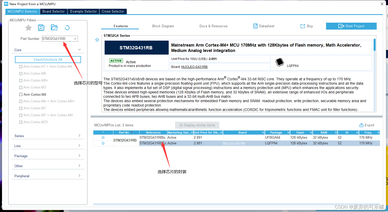
打开Cube 选择芯片的型号STM32G431RB

芯片型号的选型
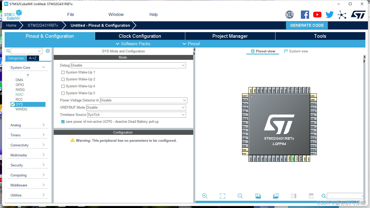
systick的配置 :Debug默认配置就好了
如果芯片采用F1(M3)系列的 就有讲究 如果选择默认的配置,程序就只可以烧了一次,如果想再次烧了的话,就只能串口烧录才会边正常
如果是F4(M4)以上的系列 就可以不用配置那个模式
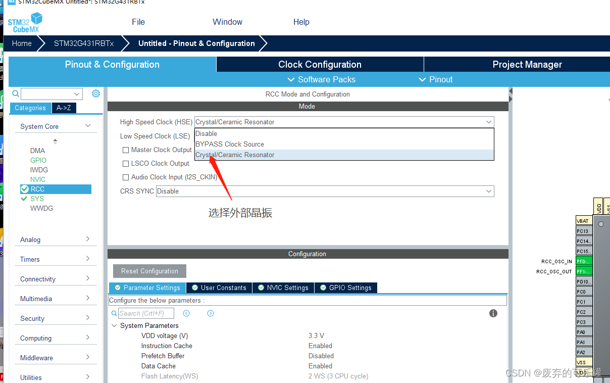
时钟的配置
选择高速外部晶振 ----->外部晶振
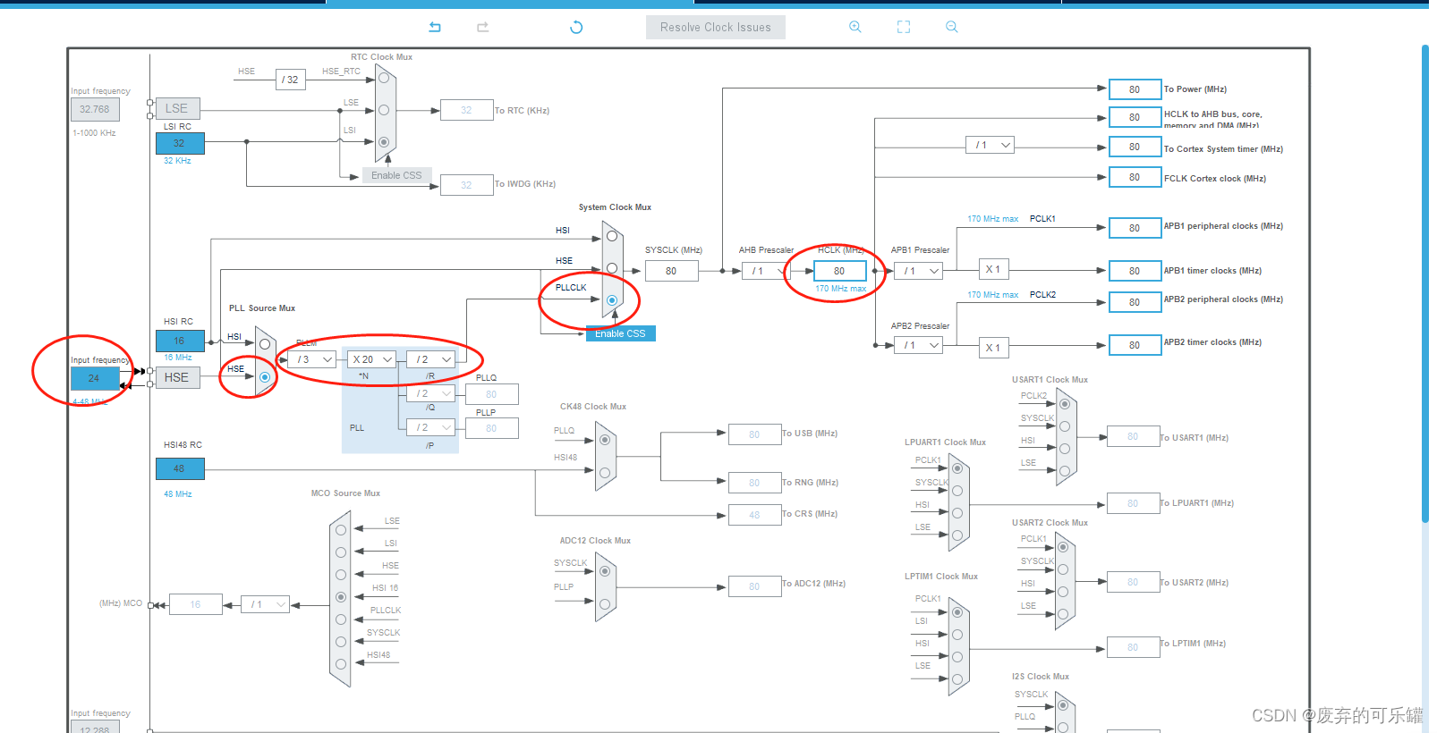
时钟树的配置
外部晶振用24M 因为这是由于外部的电路决定的
需要改的 选择HSE PLLCLK
24 3 20 最后得到的要80M!!!
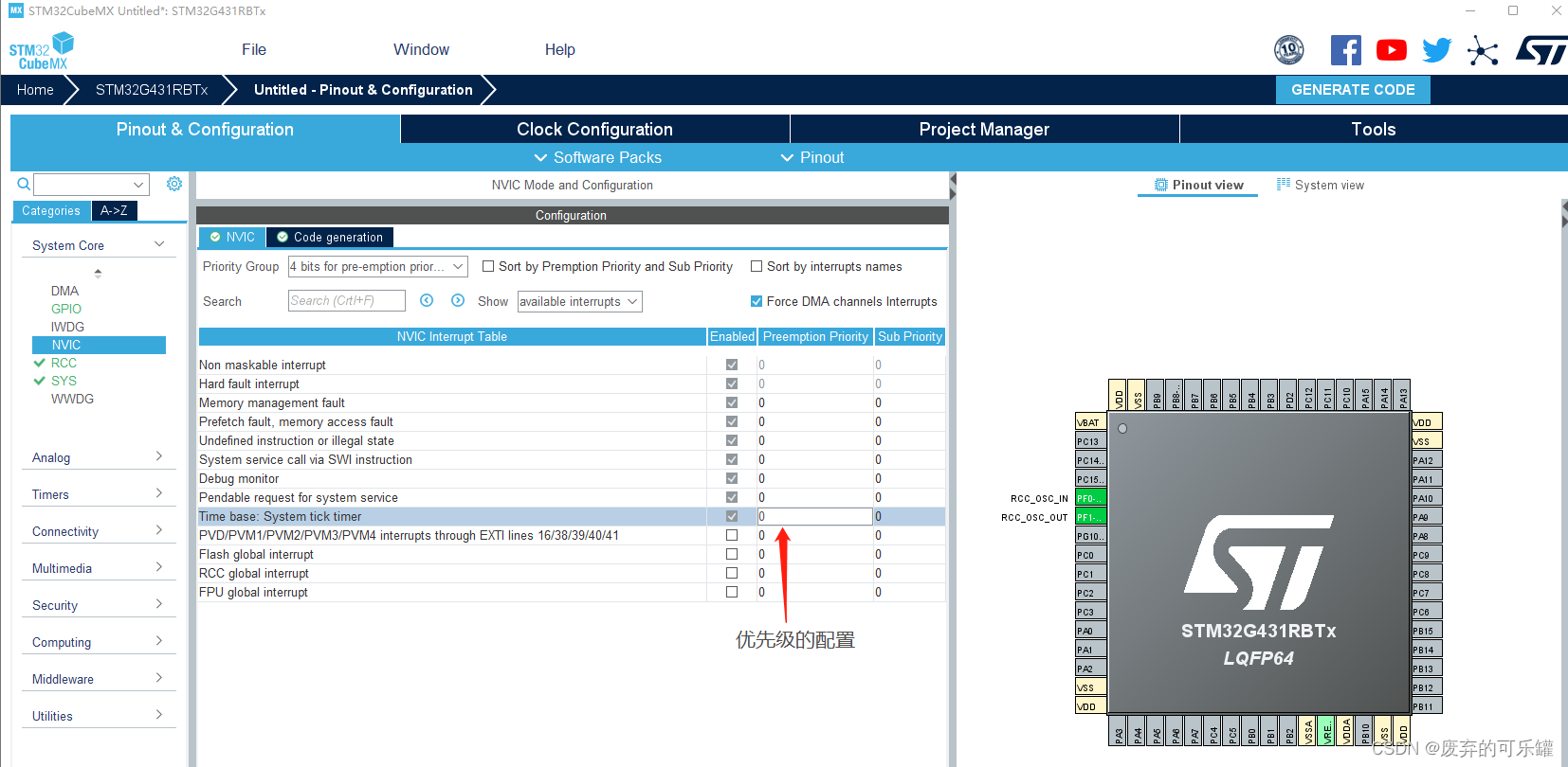
中断分组的优先级配置
中断的分组都统一为4bit(如果systick的优先级改了15变成0的话 delay的优先级后面就不用改了 如果没改的话 就要改!!!)
因为这个涉及到了在串口里面写延时的函数,如果想用延时函数的话,systick的优先级一定要最高,不然程序会被卡在延时函数,不能够完成串口里面的功能
电路原理图
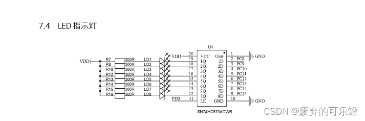
我们可以看出到PC8-PC15是单片机的led引脚,当给高电平的时候,LED不亮
PD2为芯片的锁存器的引脚,当为低电平的时候,数据不能通过,高电平数据可以通过。
总的来说就是:
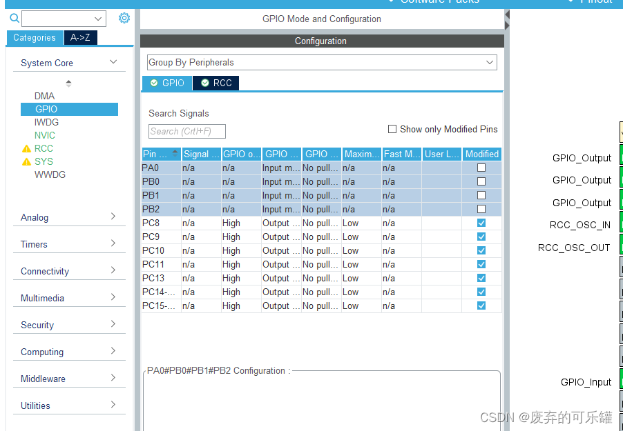
LED的代码配置
GPIO_Output(PC8~PC15)高电平:不亮
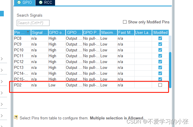
GPIO_Output(PD2)低电平:不能写数据
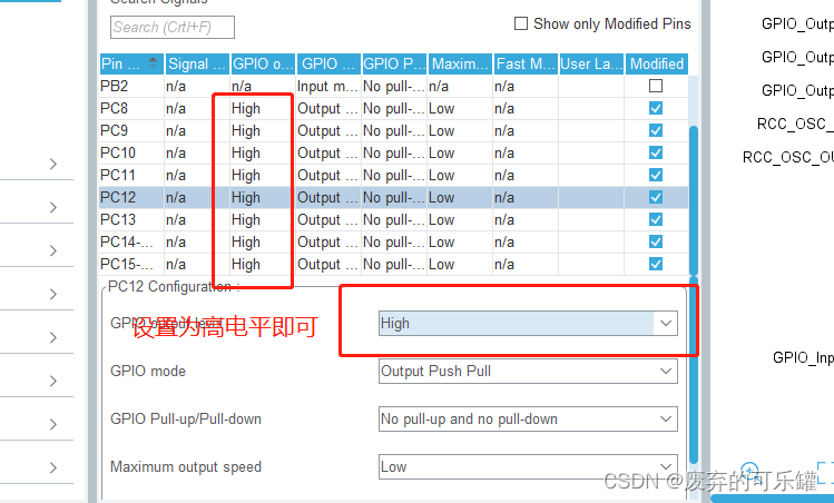
PD2一定不要忘记了!!!
Key按键的IO口配置
原理图
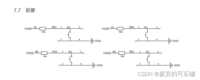
按键的代码配置
GPIO_Input(PA0 PB0 PB1 PB2)
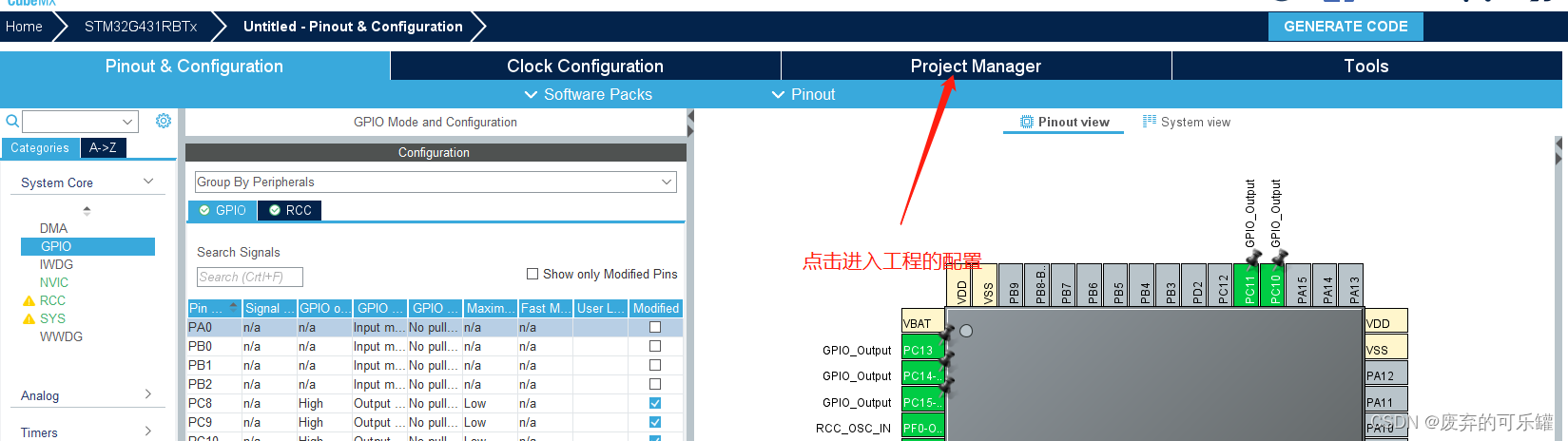
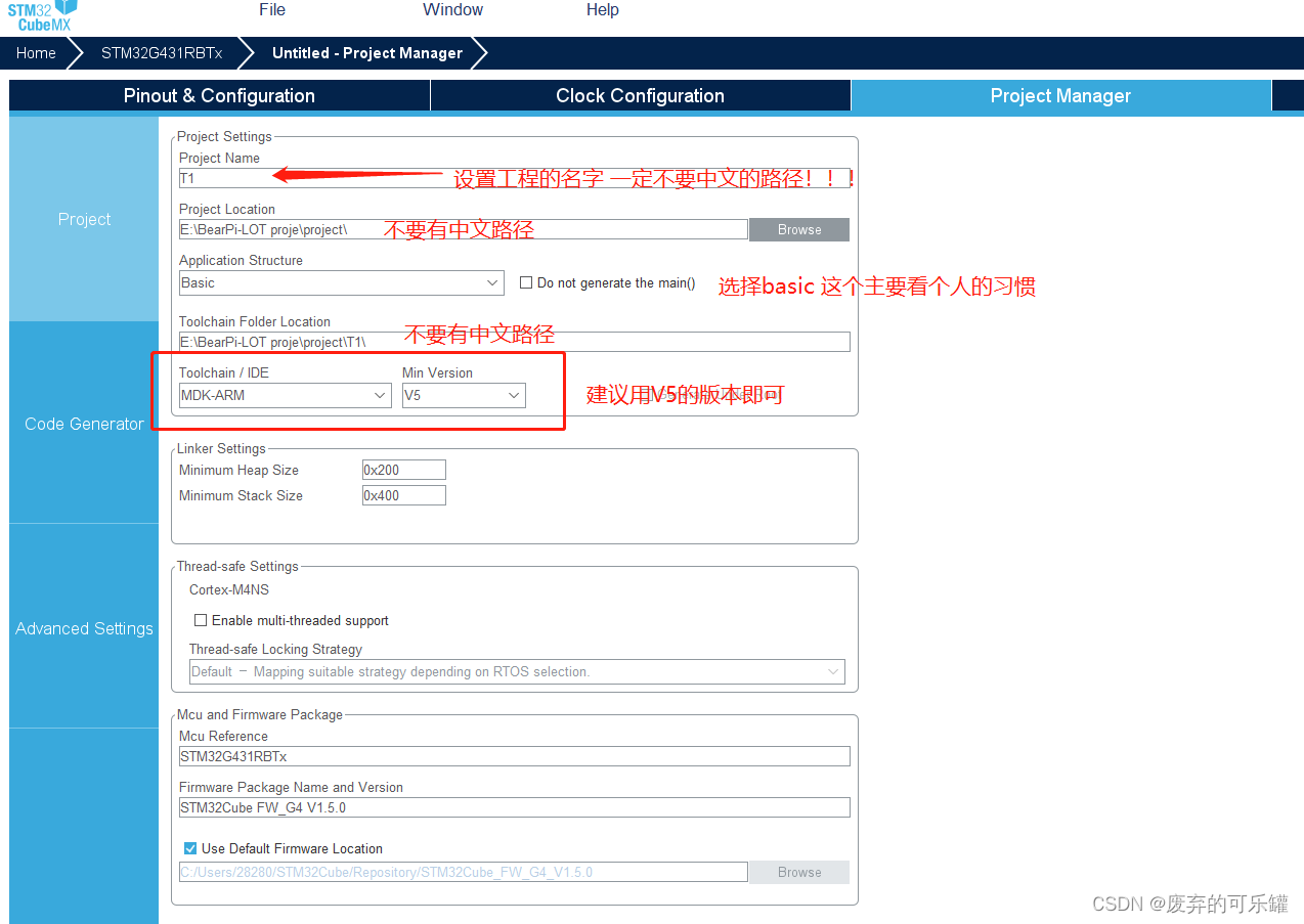
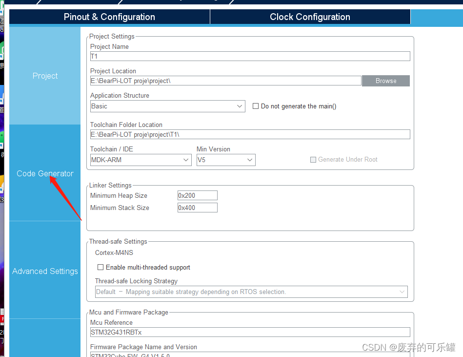
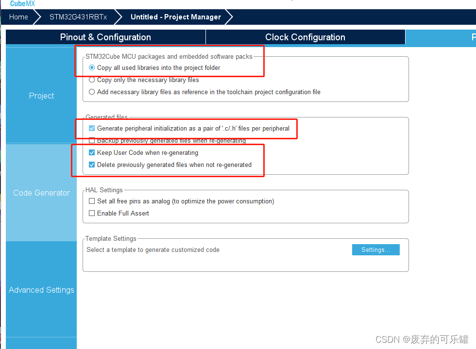
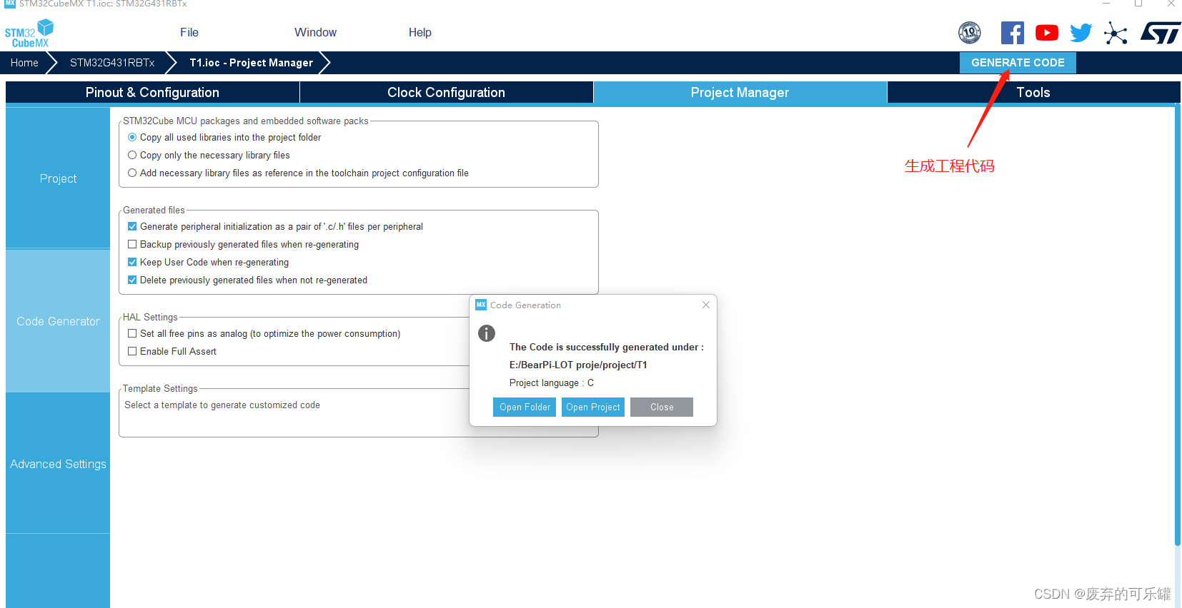
生成工程配置的选择
这里的配置都是通常的配置 按照个人的习惯即可
按键和点灯的 代码的配置
底层代码的分析:gpio文件里面写就好了
ucled这个值是为了方便我们对io口进行直接的点灯的操作
//函数名:LED_Disp
//入口参数:ucLed
//出口参数:void
//参数功能:LD8-LD1对应ucLed的8个位
void LED_Disp(uint8_t ucLed)
{
	//**将所有的灯熄灭
	HAL_GPIO_WritePin(GPIOC, GPIO_PIN_13|GPIO_PIN_14|GPIO_PIN_15|GPIO_PIN_8
                          |GPIO_PIN_9|GPIO_PIN_10|GPIO_PIN_11|GPIO_PIN_12, GPIO_PIN_SET);
	HAL_GPIO_WritePin(GPIOD,GPIO_PIN_2,GPIO_PIN_SET);
	HAL_GPIO_WritePin(GPIOD,GPIO_PIN_2,GPIO_PIN_RESET);


	//根据ucLed的数值点亮相应的灯
	HAL_GPIO_WritePin(GPIOC,ucLed<<8,GPIO_PIN_RESET);
	HAL_GPIO_WritePin(GPIOD,GPIO_PIN_2,GPIO_PIN_SET);
	HAL_GPIO_WritePin(GPIOD,GPIO_PIN_2,GPIO_PIN_RESET);
}
//KEY按键子函数
uint8_t Key_Scan(void)
{
unsigned char unKey_Val = 0;
if(HAL_GPIO_ReadPin(GPIOB,GPIO_PIN_0) == GPIO_PIN_RESET)
unKey_Val = 1;
if(HAL_GPIO_ReadPin(GPIOB,GPIO_PIN_1) == GPIO_PIN_RESET)
unKey_Val = 2;
if(HAL_GPIO_ReadPin(GPIOB,GPIO_PIN_2) == GPIO_PIN_RESET)
unKey_Val = 3;
if(HAL_GPIO_ReadPin(GPIOA,GPIO_PIN_0) == GPIO_PIN_RESET)
unKey_Val = 4;
return unKey_Val;
}main函数的分析:
变量声明区
/* Private macro -------------------------------------------------------------*/
/* USER CODE BEGIN PM */
//***全局变量声明区
//**减速变量
__IO uint32_t uwTick_Led = 0;//控制Led_Proc的执行速度
__IO uint32_t uwTick_Key = 0;//控制Key_Proc的执行速度
//*LED专属变量
uint8_t ucLed =0;
//*按键专属变量
uint8_t ucKey_Val,ucKey_Down,ucKey_Up,ucKey_Old;
/* USER CODE END PM */
/* Private variables ---------------------------------------------------------*/
/* USER CODE BEGIN PV */
//私有变量区
/* USER CODE END PV */
/* Private function prototypes -----------------------------------------------*/
void SystemClock_Config(void);
/* USER CODE BEGIN PFP */
//***子函数声明区
void Led_Proc(void);
void Key_Proc(void);
/* USER CODE END PFP */while里面编写的函数
while (1)
{
/* USER CODE END WHILE */
/* USER CODE BEGIN 3 */
Key_Proc();
Led_Proc();
}
/* USER CODE END 3 */自己编写的函数
为什么要运用到减速函数呢?
因为减速函数可以当一个延时的作用 不用没错whie里面都运行相应的子函数,节省cup的资源,另外uwTick(全局变量来的)这个值是系统定时间自带的一个计数的,如果有不懂的可以百度了解下。它是一个向上计数的,在系统运行的时候,不断加一,用来当延时函数非常的方便!!!
PS:Key_Proc里面涉及到了三行代码 只要去看我之前写的博客 就知道原理
/* USER CODE BEGIN 4 */
//***led扫描子函数
void Led_Proc(void)
{
if((uwTick - uwTick_Led) < 200) return; //减速函数
uwTick_Led = uwTick;
LED_Disp(ucLed);
}
//***按键扫描子函数
void Key_Proc(void)
{
if((uwTick - uwTick_Key) < 50) return; //减速函数
uwTick_Key = uwTick;
ucKey_Val = Key_Scan();
ucKey_Down = ucKey_Val & (ucKey_Old ^ ucKey_Val);
ucKey_Up = ~ucKey_Val & (ucKey_Old ^ ucKey_Val);
ucKey_Old = ucKey_Val;
if(ucKey_Down == 4)
{
ucLed = 0x88;
}
if(ucKey_Down == 3)
{
ucLed = 0x00;;
}
}
/* USER CODE END 4 */LED的配置 在gpio.c 和gpio.h0修改文件即可,主要配置LED和KEY的相关底层代码
gpio.c
/* USER CODE BEGIN Header */
/**
******************************************************************************
* @file gpio.c
* @brief This file provides code for the configuration
* of all used GPIO pins.
******************************************************************************
* @attention
*
* Copyright (c) 2022 STMicroelectronics.
* All rights reserved.
*
* This software is licensed under terms that can be found in the LICENSE file
* in the root directory of this software component.
* If no LICENSE file comes with this software, it is provided AS-IS.
*
******************************************************************************
*/
/* USER CODE END Header */
/* Includes ------------------------------------------------------------------*/
#include "gpio.h"
/* USER CODE BEGIN 0 */
/* USER CODE END 0 */
/*----------------------------------------------------------------------------*/
/* Configure GPIO */
/*----------------------------------------------------------------------------*/
/* USER CODE BEGIN 1 */
/* USER CODE END 1 */
/** Configure pins as
* Analog
* Input
* Output
* EVENT_OUT
* EXTI
*/
void MX_GPIO_Init(void)
{
GPIO_InitTypeDef GPIO_InitStruct = {0};
/* GPIO Ports Clock Enable */
__HAL_RCC_GPIOC_CLK_ENABLE();
__HAL_RCC_GPIOF_CLK_ENABLE();
__HAL_RCC_GPIOA_CLK_ENABLE();
__HAL_RCC_GPIOB_CLK_ENABLE();
__HAL_RCC_GPIOD_CLK_ENABLE();
/*Configure GPIO pin Output Level */
HAL_GPIO_WritePin(GPIOC, GPIO_PIN_13|GPIO_PIN_14|GPIO_PIN_15|GPIO_PIN_8
|GPIO_PIN_9|GPIO_PIN_10|GPIO_PIN_11|GPIO_PIN_12, GPIO_PIN_SET);
/*Configure GPIO pin Output Level */
HAL_GPIO_WritePin(GPIOD, GPIO_PIN_2, GPIO_PIN_RESET);
/*Configure GPIO pins : PC13 PC14 PC15 PC8
PC9 PC10 PC11 PC12 */
GPIO_InitStruct.Pin = GPIO_PIN_13|GPIO_PIN_14|GPIO_PIN_15|GPIO_PIN_8
|GPIO_PIN_9|GPIO_PIN_10|GPIO_PIN_11|GPIO_PIN_12;
GPIO_InitStruct.Mode = GPIO_MODE_OUTPUT_PP;
GPIO_InitStruct.Pull = GPIO_NOPULL;
GPIO_InitStruct.Speed = GPIO_SPEED_FREQ_LOW;
HAL_GPIO_Init(GPIOC, &GPIO_InitStruct);
/*Configure GPIO pin : PA0 */
GPIO_InitStruct.Pin = GPIO_PIN_0;
GPIO_InitStruct.Mode = GPIO_MODE_INPUT;
GPIO_InitStruct.Pull = GPIO_NOPULL;
HAL_GPIO_Init(GPIOA, &GPIO_InitStruct);
/*Configure GPIO pins : PB0 PB1 PB2 */
GPIO_InitStruct.Pin = GPIO_PIN_0|GPIO_PIN_1|GPIO_PIN_2;
GPIO_InitStruct.Mode = GPIO_MODE_INPUT;
GPIO_InitStruct.Pull = GPIO_NOPULL;
HAL_GPIO_Init(GPIOB, &GPIO_InitStruct);
/*Configure GPIO pin : PD2 */
GPIO_InitStruct.Pin = GPIO_PIN_2;
GPIO_InitStruct.Mode = GPIO_MODE_OUTPUT_PP;
GPIO_InitStruct.Pull = GPIO_NOPULL;
GPIO_InitStruct.Speed = GPIO_SPEED_FREQ_LOW;
HAL_GPIO_Init(GPIOD, &GPIO_InitStruct);
}
/* USER CODE BEGIN 2 */
//函数名:LED_Disp
//入口参数:ucLed
//出口参数:void
//参数功能:LD8-LD1对应ucLed的8个位
void LED_Disp(uint8_t ucLed)
{
//**将所有的灯熄灭
HAL_GPIO_WritePin(GPIOC, GPIO_PIN_13|GPIO_PIN_14|GPIO_PIN_15|GPIO_PIN_8
|GPIO_PIN_9|GPIO_PIN_10|GPIO_PIN_11|GPIO_PIN_12, GPIO_PIN_SET);
HAL_GPIO_WritePin(GPIOD,GPIO_PIN_2,GPIO_PIN_SET);
HAL_GPIO_WritePin(GPIOD,GPIO_PIN_2,GPIO_PIN_RESET);
//根据ucLed的数值点亮相应的灯
HAL_GPIO_WritePin(GPIOC,ucLed<<8,GPIO_PIN_RESET);
HAL_GPIO_WritePin(GPIOD,GPIO_PIN_2,GPIO_PIN_SET);
HAL_GPIO_WritePin(GPIOD,GPIO_PIN_2,GPIO_PIN_RESET);
}
//KEY按键子函数
uint8_t Key_Scan(void)
{
	unsigned char unKey_Val = 0;

	if(HAL_GPIO_ReadPin(GPIOB,GPIO_PIN_0) == GPIO_PIN_RESET)
		unKey_Val = 1;

	if(HAL_GPIO_ReadPin(GPIOB,GPIO_PIN_1) == GPIO_PIN_RESET)
		unKey_Val = 2;

	if(HAL_GPIO_ReadPin(GPIOB,GPIO_PIN_2) == GPIO_PIN_RESET)
		unKey_Val = 3;

	if(HAL_GPIO_ReadPin(GPIOA,GPIO_PIN_0) == GPIO_PIN_RESET)
		unKey_Val = 4;

	return unKey_Val;
}
/* USER CODE END 2 */
gpio.h
/* USER CODE BEGIN Header */
/**
******************************************************************************
* @file gpio.h
* @brief This file contains all the function prototypes for
* the gpio.c file
******************************************************************************
* @attention
*
* Copyright (c) 2022 STMicroelectronics.
* All rights reserved.
*
* This software is licensed under terms that can be found in the LICENSE file
* in the root directory of this software component.
* If no LICENSE file comes with this software, it is provided AS-IS.
*
******************************************************************************
*/
/* USER CODE END Header */
/* Define to prevent recursive inclusion -------------------------------------*/
#ifndef __GPIO_H__
#define __GPIO_H__
#ifdef __cplusplus
extern "C" {
#endif
/* Includes ------------------------------------------------------------------*/
#include "main.h"
/* USER CODE BEGIN Includes */
/* USER CODE END Includes */
/* USER CODE BEGIN Private defines */
/* USER CODE END Private defines */
void MX_GPIO_Init(void);
/* USER CODE BEGIN Prototypes */
void Led_Disp(unsigned char ucLed);
uint8_t Key_Scan(void);
/* USER CODE END Prototypes */
#ifdef __cplusplus
}
#endif
#endif /*__ GPIO_H__ */
主函数编写的相关代码:
/* USER CODE BEGIN Header */
/**
******************************************************************************
* @file : main.c
* @brief : Main program body
******************************************************************************
* @attention
*
* Copyright (c) 2022 STMicroelectronics.
* All rights reserved.
*
* This software is licensed under terms that can be found in the LICENSE file
* in the root directory of this software component.
* If no LICENSE file comes with this software, it is provided AS-IS.
*
******************************************************************************
*/
/* USER CODE END Header */
/* Includes ------------------------------------------------------------------*/
#include "main.h"
#include "gpio.h"
/* Private includes ----------------------------------------------------------*/
/* USER CODE BEGIN Includes */
/* USER CODE END Includes */
/* Private typedef -----------------------------------------------------------*/
/* USER CODE BEGIN PTD */
/* USER CODE END PTD */
/* Private define ------------------------------------------------------------*/
/* USER CODE BEGIN PD */
/* USER CODE END PD */
/* Private macro -------------------------------------------------------------*/
/* USER CODE BEGIN PM */
//***全局变量声明区
//**减速变量
__IO uint32_t uwTick_Led = 0;//控制Led_Proc的执行速度
__IO uint32_t uwTick_Key = 0;//控制Key_Proc的执行速度

//*LED专属变量
uint8_t ucLed =0;

//*按键专属变量
uint8_t ucKey_Val,ucKey_Down,ucKey_Up,ucKey_Old;

/* USER CODE END PM */

/* Private variables ---------------------------------------------------------*/

/* USER CODE BEGIN PV */
//私有变量区


/* USER CODE END PV */

/* Private function prototypes -----------------------------------------------*/
void SystemClock_Config(void);
/* USER CODE BEGIN PFP */
//***子函数声明区

void Led_Proc(void);
void Key_Proc(void);

/* USER CODE END PFP */
/* Private user code ---------------------------------------------------------*/
/* USER CODE BEGIN 0 */
/* USER CODE END 0 */
/**
* @brief The application entry point.
* @retval int
*/
int main(void)
{
/* USER CODE BEGIN 1 */
/* USER CODE END 1 */
/* MCU Configuration--------------------------------------------------------*/
/* Reset of all peripherals, Initializes the Flash interface and the Systick. */
HAL_Init();
/* USER CODE BEGIN Init */
/* USER CODE END Init */
/* Configure the system clock */
SystemClock_Config();
/* USER CODE BEGIN SysInit */
/* USER CODE END SysInit */
/* Initialize all configured peripherals */
MX_GPIO_Init();
/* USER CODE BEGIN 2 */
/* USER CODE END 2 */
/* Infinite loop */
/* USER CODE BEGIN WHILE */
while (1)
  {
    /* USER CODE END WHILE */

    /* USER CODE BEGIN 3 */
		Key_Proc();
		Led_Proc();
  }
  /* USER CODE END 3 */
}
/**
* @brief System Clock Configuration
* @retval None
*/
void SystemClock_Config(void)
{
RCC_OscInitTypeDef RCC_OscInitStruct = {0};
RCC_ClkInitTypeDef RCC_ClkInitStruct = {0};
/** Configure the main internal regulator output voltage
*/
HAL_PWREx_ControlVoltageScaling(PWR_REGULATOR_VOLTAGE_SCALE1);
/** Initializes the RCC Oscillators according to the specified parameters
* in the RCC_OscInitTypeDef structure.
*/
RCC_OscInitStruct.OscillatorType = RCC_OSCILLATORTYPE_HSE;
RCC_OscInitStruct.HSEState = RCC_HSE_ON;
RCC_OscInitStruct.PLL.PLLState = RCC_PLL_ON;
RCC_OscInitStruct.PLL.PLLSource = RCC_PLLSOURCE_HSE;
RCC_OscInitStruct.PLL.PLLM = RCC_PLLM_DIV3;
RCC_OscInitStruct.PLL.PLLN = 20;
RCC_OscInitStruct.PLL.PLLP = RCC_PLLP_DIV2;
RCC_OscInitStruct.PLL.PLLQ = RCC_PLLQ_DIV2;
RCC_OscInitStruct.PLL.PLLR = RCC_PLLR_DIV2;
if (HAL_RCC_OscConfig(&RCC_OscInitStruct) != HAL_OK)
{
Error_Handler();
}
/** Initializes the CPU, AHB and APB buses clocks
*/
RCC_ClkInitStruct.ClockType = RCC_CLOCKTYPE_HCLK|RCC_CLOCKTYPE_SYSCLK
|RCC_CLOCKTYPE_PCLK1|RCC_CLOCKTYPE_PCLK2;
RCC_ClkInitStruct.SYSCLKSource = RCC_SYSCLKSOURCE_PLLCLK;
RCC_ClkInitStruct.AHBCLKDivider = RCC_SYSCLK_DIV1;
RCC_ClkInitStruct.APB1CLKDivider = RCC_HCLK_DIV1;
RCC_ClkInitStruct.APB2CLKDivider = RCC_HCLK_DIV1;
if (HAL_RCC_ClockConfig(&RCC_ClkInitStruct, FLASH_LATENCY_2) != HAL_OK)
{
Error_Handler();
}
}
/* USER CODE BEGIN 4 */
//***led扫描子函数

void Led_Proc(void)
{
	if((uwTick - uwTick_Led) < 200) return; //减速函数
		uwTick_Led = uwTick;

	LED_Disp(ucLed);
}


//***按键扫描子函数

void Key_Proc(void)
{
	if((uwTick - uwTick_Key) < 50) return; //减速函数
		uwTick_Key = uwTick;

	ucKey_Val = Key_Scan();
	ucKey_Down = ucKey_Val & (ucKey_Old ^ ucKey_Val);
	ucKey_Up = ~ucKey_Val & (ucKey_Old ^ ucKey_Val);
	ucKey_Old = ucKey_Val;

	if(ucKey_Down == 4)
	{
		 ucLed = 0x88;
	}
	if(ucKey_Down == 3)
	{
		 ucLed = 0x00;;
	}

}

/* USER CODE END 4 */
/**
* @brief This function is executed in case of error occurrence.
* @retval None
*/
void Error_Handler(void)
{
/* USER CODE BEGIN Error_Handler_Debug */
/* User can add his own implementation to report the HAL error return state */
__disable_irq();
while (1)
{
}
/* USER CODE END Error_Handler_Debug */
}
#ifdef USE_FULL_ASSERT
/**
* @brief Reports the name of the source file and the source line number
* where the assert_param error has occurred.
* @param file: pointer to the source file name
* @param line: assert_param error line source number
* @retval None
*/
void assert_failed(uint8_t *file, uint32_t line)
{
/* USER CODE BEGIN 6 */
/* User can add his own implementation to report the file name and line number,
ex: printf("Wrong parameters value: file %s on line %d\r\n", file, line) */
/* USER CODE END 6 */
}
#endif /* USE_FULL_ASSERT */
 https://download.csdn.net/download/pixjaofiaf62/85355846