文章目录
- 参考视频:Bilibili summer课堂,网络工程师相关视频
一. 环境安装
参考:华为 eNSP 模拟器安装教程
下面是安装过程中遇到的问题:
- winpcap无法安装(提示已存在):在控制面板的程序与卸载里面卸载winPcap,然后再安装
- 安装VirtualBox提示“此应用无法在设备上运行 :后续可能导致内存完整性无法开启,需要卸载VirtualBox
测试可以运行成功:
二. 设备配置
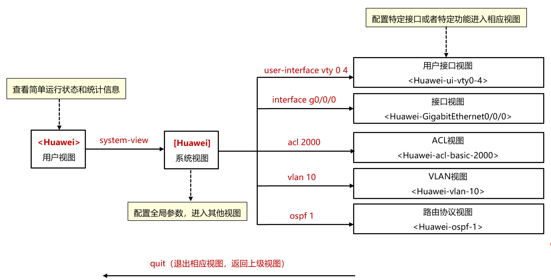
- 配置视图
- 设备登录配置
<AR> system-view //进入系统模式
[AR] sysname Huawei
[Huawei] telnet server enable //开启设备telnet功能
[Huawei] user-interface vty 0 4 //开启登录端口0-4
[Huawei-ui-vty0-4] protocol inbound telnet //通过telnet协议登录
[Huawei-ui-vty0-4] authentication-mode aaa //认证方式为aaa
[Huawei] aaa //启用aaa
[Huawei-aaa] local-user admin123 password admin123 //配置用户名密码
[Huawei-aaa] local-user admin123 service-type telnet//用户用于telnet
[Huawei-aaa] local-user admin123 privilege level 15 //用户等级为15
[Huawei-aaa] quit //退出来
- 掩码和反掩码
- 使用掩码:IP地址强相关
IP地址配置: ip address 192.168.1.1255.255.255.0或 ip address 192.168.1.124
DHCP配置:network 192.168.1.0 mask255.255.255.0或 network 192.168.1.0 mask24 - 使用反掩码
ACL:rule 10 permit source 192.168.1.10或 rule 10 permit source 192.168.1.10.0.0.0
ACL:rule 10 permit source 192.168.1.00.0.0.255
OSPF路由宣告:network 192.168.1.00.0.0.255//宣告1.0网段 - RIP路由宣告不需要掩码或反掩码,宣告主类网络(A/B/C主类IP地址掩码分别为8/16/24)
network 10.0.0.0
network 172.16.0.0
network 192.168.1.0
三. 实验配置
01 动态主机配置协议DHCP
- DHCP: 实现网络动态分配IP地址,主机无需配置,从服务器端获取地址,可实现接入网络后即插即用
- 配置实验
<Huawei>system-view
Enter system view, return user view with Ctrl+Z.
[Huawei]sysname SW  //命名

//可以关闭提示消息
[SW]undo info-center enable
Info: Information center is disabled.

[SW]vlan 10   //创建vlan
[SW-vlan10]vlan 20

//可以vlan batch 10 20 同时创建多个vlan
//显示vlan列表
[SW-vlan20]display vlan summary
static vlan:
Total 3 static vlan.
  1 10 20

dynamic vlan:
Total 0 dynamic vlan.

reserved vlan:
Total 0 reserved vlan.

//配置vlan的虚拟接口,作为PC1和PC2的默认网关
//有些命令可以简写,不过学习还是记住比较好
[SW]interface Vlanif 10
[SW-Vlanif10]ip add 192.168.10.254 24
[SW-Vlanif10]int vlan 20
[SW-Vlanif20]ip add 192.168.20.254 24
[SW-Vlanif20]quit
//配置接口
[SW]int GigabitEthernet 0/0/1
[SW-GigabitEthernet0/0/1]port link-type access //p l a
[SW-GigabitEthernet0/0/1]port default vlan 10
[SW-GigabitEthernet0/0/1]int g0/0/2
[SW-GigabitEthernet0/0/2]port link-type access
[SW-GigabitEthernet0/0/2]port default vlan 20
[SW-GigabitEthernet0/0/2]quit
使用三层交换机作为DHCP服务器
- 基于接口的配置
[SW]dhcp enable  //开启DHCP
Info: The operation may take a few seconds. Please wait for a moment.done.

[SW]interface Vlanif 10
//[SW-Vlanif10]dhcp server dns-list 8.8.8.8
//Error:Please configure dhcp select interface first.
[SW-Vlanif10]dhcp select ?
  global     Local server
  interface  Interface server pool
  relay      DHCP relay

//接口采用接口地址池的DHCP服务器端功能
[SW-Vlanif10]dhcp select interface
[SW-Vlanif10]dhcp server excluded-ip-address 192.168.10.101 192.168.10.253 //排除的ip地址范围
[SW-Vlanif10]dhcp server lease day 8 //租期,缺省为1天
[SW-Vlanif10]dhcp server dns-list 8.8.8.8

 //查看已配置的dhcp信息
[SW-Vlanif10]display this
#
interface Vlanif10
 ip address 192.168.10.254 255.255.255.0
 dhcp select interface
 dhcp server excluded-ip-address 192.168.10.101 192.168.10.253
 dhcp server lease day 8 hour 0 minute 0
 dhcp server dns-list 8.8.8.8
#
return
抓包PC1: 获得了192.168.10.100的地址 (华为设备会先获取大的ip地址)
- 基于全局地址池
[SW]interface Vlanif 20
[SW-Vlanif20]dhcp select global   //全局
[SW-Vlanif20]quit

[SW]ip pool ?
  STRING<1-64>  Pool name
//创建全局地址池
[SW]ip pool 20

//[SW-ip-pool-20]network 192.169.20.0 mask 24  写错ip了
//[SW-ip-pool-20]undo network
[SW-ip-pool-20]network 192.168.20.0 mask 24
[SW-ip-pool-20]gateway-list 192.168.20.254  //网关
[SW-ip-pool-20]dns-list 9.9.9.9
[SW-ip-pool-20]lease 10 //租期10天
[SW-ip-pool-20]excluded-ip-address 192.168.20.151 192.168.20.253 //排除网段
[SW-ip-pool-20]display this
#
ip pool 20
 gateway-list 192.168.20.254
 network 192.168.20.0 mask 255.255.255.0
 excluded-ip-address 192.168.20.151 192.168.20.253
 lease day 10 hour 0 minute 0
 dns-list 9.9.9.9
#
return
[SW-ip-pool-20]quit
[SW]interface Vlanif 20
[SW-Vlanif20]display this
#
interface Vlanif20
 ip address 192.168.20.254 255.255.255.0
 dhcp select global
#
return
PC2获取ip地址:
02 ACL原理与配置
- ACL是由一系列permit或deny语句组成的、有序规则的列表
- ACL是一个匹配工具,能够对报文进行匹配和区分,与防火墙、路由策略、Qos、流量过滤等其他技术结合使用
- 规则编号:ACL规则相应的编号,步长缺省为5
- 通配符
规则:0表示匹配;1表示“随机分配
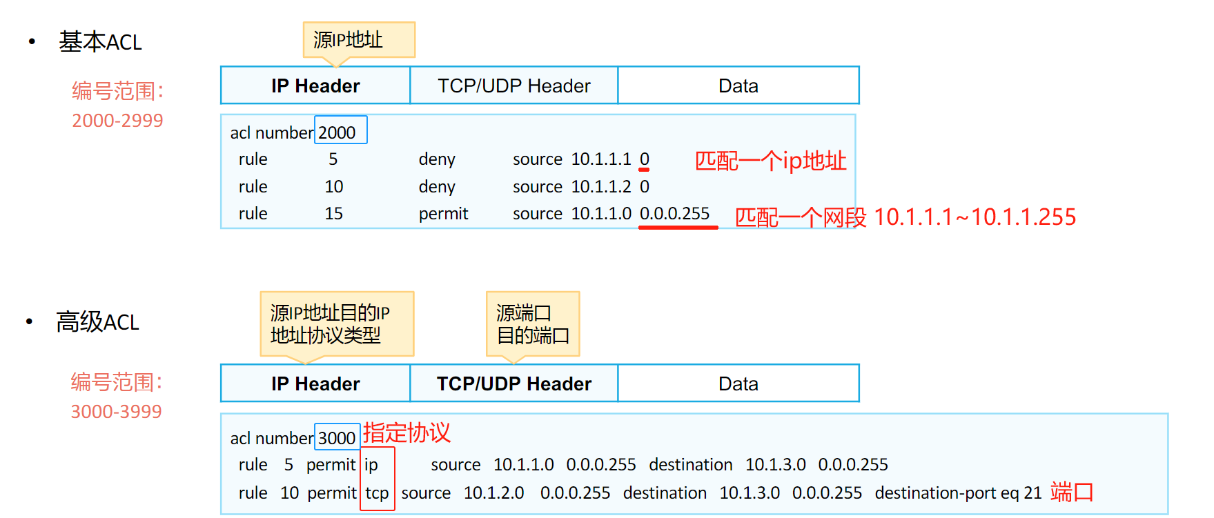
- ACL的分类
| 分类 | 编号范围 | 规则定义描述 |
|---|---|---|
| 基本ACL | 2000~2999 | 仅使用报文的源IP地址、分片信息和生效时间段信息来定义规则 |
| 高级 ACL | 3000~3999 | 可使用IPv4报文的源IP地址、目的IP地址、IP协议类型、ICMP类型、TCP源/目的端口号、UDP源/目的端口号、生效时间段等来定义规则 |
4. ACL应用的位置
- 配置实验:
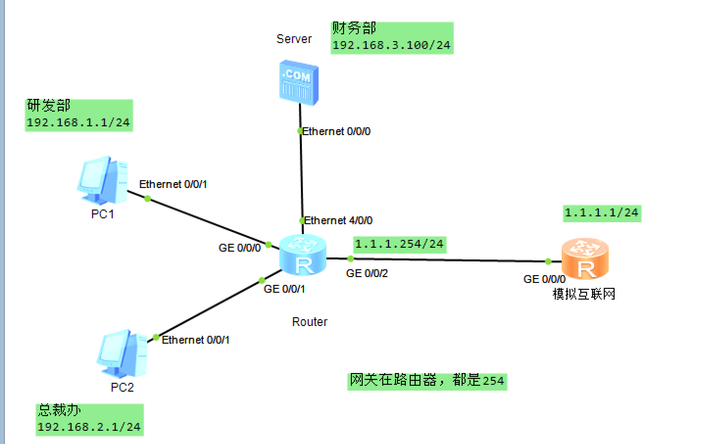
拓扑:对于路由器如果缺少Ge或者Ethernet口,可以在配置里拖拽适合的模块进行配置
# 配置路由器端口

<Huawei>system-view
[Huawei]sysname Router
[Router]int GigabitEthernet 0/0/0
[Router-GigabitEthernet0/0/0]ip add 192.168.1.254 24
[Router-GigabitEthernet0/0/0]quit
[Router]int GigabitEthernet 0/0/1
[Router-GigabitEthernet0/0/1]ip add 192.168.2.254 24
[Router]int GigabitEthernet 0/0/2
[Router-GigabitEthernet0/0/2]ip add 1.1.1.254 24
[Router]interface Ethernet 4/0/0
[Router-Ethernet4/0/0]ip add 192.168.3.254 24

# 网络互通,在Internet端(用路由器模拟的)配置一个静态路由
[Huawei]ip route-static 0.0.0.0 0 1.1.1.254
此时各设备之间可以ping通: 路由器连接的PC和服务器可以直接ping,两个路由器之间处于不同网段,才需要配置静态路由
# 配置ACL并应用在连接服务器的端口

[Router]acl 3000
//拒绝研发部访问
[Router-acl-adv-3000]rule 10 deny ip source 192.168.1.0 0.0.0.255 destination 19
2.168.3.100 0   //0可以代替0.0.0.0
//运行总裁办访问
[Router-acl-adv-3000]rule 20 permit ip source 192.168.2.0 0.0.0.255 destination
192.168.3.100 0
//拒绝外部互联网的访问
[Router-acl-adv-3000]rule 30 deny ip source any destination 192.168.3.100 0
[Router-acl-adv-3000]qu
[Router]interface e 4/0/0
//路由器接口应用ACL:对 e4/0/0 出口的流量做限制
[Router-Ethernet4/0/0]traffic-filter outbound acl 3000
此时,只有总裁办的PC可以访问财务部服务器,其他流量会被拒绝,但PC可以正常访问外部网络1.1.1.1
03 网络地址转换NAT
- NAT产生背景:NAT缓解了IPV4地址短缺的问题,也提升了内网的安全性
- 地址
- NAT分类
- 静态NAT:
每个私有地址都有一个与之对应并且固定的公有地址(私有地址1 vs 1公有地址),不能减少公网IP使用 - 动态NAT: 所有可用的公有地址组成地址池,当内部主机访问外部网络时临时分配一个地址池中未使用的地址(不会转换端口号,No-PAT)
NAPT(Network Address and Port Translation,网络地址端口转换):从地址池中选择地址进行地址转换时不仅转换IP地址,同时也会对端口号进行转换,从而实现公有地址与私有地址的1:n映射EasyIP: 实现原理和NAPT一样,区别在于EasyIP没有地址池的概念,使用接口地址作为NAT转换的公有地址
Easy IP适用于不具备固定公网IP地址的场景:如通过DHCP、PPPoE拨号获取地址的私有网络出口,可以直接使用获取到的动态地址进行转换NAT Server:指定[公有地址:端口]与[私有地址:端口]的一对一映射关系,将内网服务器映射到公网,外网主机主动访问[公有地址:端口]实现对内网服务器的访问
- 配置实验
- 拓扑
- 互联的设备可以ping通
# 配置AR1
<Huawei>system-view
[Huawei]sysname AR1
[AR1]interface g0/0/0
[AR1-GigabitEthernet0/0/0]ip add 192.168.1.254 24
[AR1-GigabitEthernet0/0/0]qu
[AR1]interface g0/0/1
[AR1-GigabitEthernet0/0/1]ip add 12.1.1.1 24
[AR1-GigabitEthernet0/0/1]qu

# 配置AR2
<Huawei>system-view
[Huawei]sysname AR2
[AR2]interface g0/0/0
[AR2-GigabitEthernet0/0/0]ip address 12.1.1.254 24
NAT配置
- 静态NAT
# 静态NAT,直接配置一个公网ip映射到私网ip地址
[AR1]nat static global 12.1.1.2 inside 192.168.1.1
#在全局下配置则需要在接口应用NAT
[AR1]int g0/0/1
[AR1-GigabitEthernet0/0/1]nat static enable


-------------------------------------
# 也可以直接在接口处配置
//[AR1-GigabitEthernet0/0/1]undo nat static enable
//[AR1-GigabitEthernet0/0/1]qu
//[AR1]undo nat static global 12.1.1.2 inside 192.168.1.1

[AR1]interface g0/0/1
[AR1-GigabitEthernet0/0/1]nat static global 12.1.1.10 inside 192.168.1.1
此时PC1可以ping通12.1.1.254,经过AR1后,数据被转换成12.1.1.2的ip
- 动态NAT
[AR1]nat address-group ?
  INTEGER<0-7>  Index of address-group
//配置地址池,名称为1,有1.2~1.10 九个地址
[AR1]nat address-group 1 12.1.1.2 12.1.1.10
//配置ACL
[AR1]acl 2000
[AR1-acl-basic-2000]rule 10 permit source 192.168.1.0 0.0.0.255
[AR1-acl-basic-2000]qu
//在接口处应用,NAT只有outbound
[AR1]interface g0/0/1
[AR1-GigabitEthernet0/0/1]nat ?
  outbound  Specify net address translation
  server    Specify NAT server
  static    Specify static NAT
[AR1-GigabitEthernet0/0/1]nat outbound ?
  INTEGER<2000-3999>  Apply basic or advanced ACL
//把ACL 2000的源去进行转换;no-pat:不做端口转换,只做一对一的地址转换
[AR1-GigabitEthernet0/0/1]nat outbound 2000 address-group 1 no-pat
PC1进行ping,使用了地址池的12.1.1.2
- 端口NAT
//[AR1-GigabitEthernet0/0/1]undo nat outbound 2000 address-group 1 no-pat
//[AR1-GigabitEthernet0/0/1]qu
//[AR1]undo nat address-group 1

# 配置端口NAT(NAPT)
[AR1]nat address-group 1 12.1.1.2 12.1.1.2 //地址池只有一个地址
[AR1]interface g0/0/1
//与动态NAT的区别就是不加no-pat,这样地址转换时不仅转ip,也转换端口
[AR1-GigabitEthernet0/0/1]nat outbound 2000 address-group 1

---------------------------
# 此时PC1和PC2同时ping 12.1.1.154,在路由器出口处抓包,虽然都使用12.1.1.2的公网地址,但实际映射的端口不同

[AR1]display nat session all
  NAT Session Table Information:

     Protocol          : ICMP(1)
     SrcAddr   Vpn     : 192.168.1.1
     DestAddr  Vpn     : 12.1.1.254
     Type Code IcmpId  : 0   8   59763
     NAT-Info
       New SrcAddr     : 12.1.1.2
       New DestAddr    : ----
       New IcmpId      : 10261

	 Protocol          : ICMP(1)
     SrcAddr   Vpn     : 192.168.1.2
     DestAddr  Vpn     : 12.1.1.254
     Type Code IcmpId  : 0   8   59766
     NAT-Info
       New SrcAddr     : 12.1.1.2
       New DestAddr    : ----
       New IcmpId      : 10264
- EasyIP
//[AR1-GigabitEthernet0/0/1]undo nat outbound 2000 address-group 1
//[AR1-GigabitEthernet0/0/1]qu
//[AR1]undo nat address-group 1

[AR1]interface g0/0/1
[AR1-GigabitEthernet0/0/1]nat outbound 2000

[AR1]display nat session all
  NAT Session Table Information:

     Protocol          : ICMP(1)
     SrcAddr   Vpn     : 192.168.1.2
     DestAddr  Vpn     : 12.1.1.254
     Type Code IcmpId  : 0   8   60272
     NAT-Info
       New SrcAddr     : 12.1.1.1
       New DestAddr    : ----
       New IcmpId      : 10248

     Protocol          : ICMP(1)
     SrcAddr   Vpn     : 192.168.1.1
     DestAddr  Vpn     : 12.1.1.254
     Type Code IcmpId  : 0   8   60269
     NAT-Info
       New SrcAddr     : 12.1.1.1
       New DestAddr    : ----
       New IcmpId      : 10244
PC1和PC2进行ping时,直接使用出接口g0/0/1的ip地址作为公网ip,但映射端口不同(伪端口)
- NAT Server:由外访问内
//[AR1-GigabitEthernet0/0/1]undo nat outbound 2000

[AR1]interface g0/0/1
[AR1-GigabitEthernet0/0/1]nat ?
  outbound  Specify net address translation
  server    Specify NAT server
  static    Specify static NAT

# 当访问12.1.1.2的80端口时,会把数据扔到192.168.1.2 80 端口上
[AR1-GigabitEthernet0/0/1]nat server protocol tcp global 12.1.1.2 80 inside 192.168.1.2 80
04 网关冗余技术VRRP
- VRRT技术:通过把几台路由器联合组成一台虚拟的路由设备,使用一定的机制保证当前主机的下一跳路由设备出现故障时,及时将业务切换到备份路由设备,从而保持通讯的连续性和可靠性
- 应用
- 负载均衡:通过创建多个虚拟路由器,每个物理路由器在不同的VRRP组扮演不同的角色,不同的虚拟路由器的Virtual IP作为不同的内网网关地址可以实现流量转发负载分担
- VRRP与MSTP结合使用:MSTP防止环路,VRRP主备切换(不过有堆叠技术后,就不太需要MSTP了)
- VRRP监视上行端口:当设备感知上行端口或者链路发生故障时,可主动降低VRRP优先级,从而保证上行链路正常的Backup设备能通过选举切换为Master状态
- VRRP和BFD联动:当Backup设备通过BFD感知故障发生之后,不再等待Master_Down_Time计时器超时而会在BFD检测周期结束后立即切换VRRP状态,可以实现毫秒级的主备切换
- 实验配置
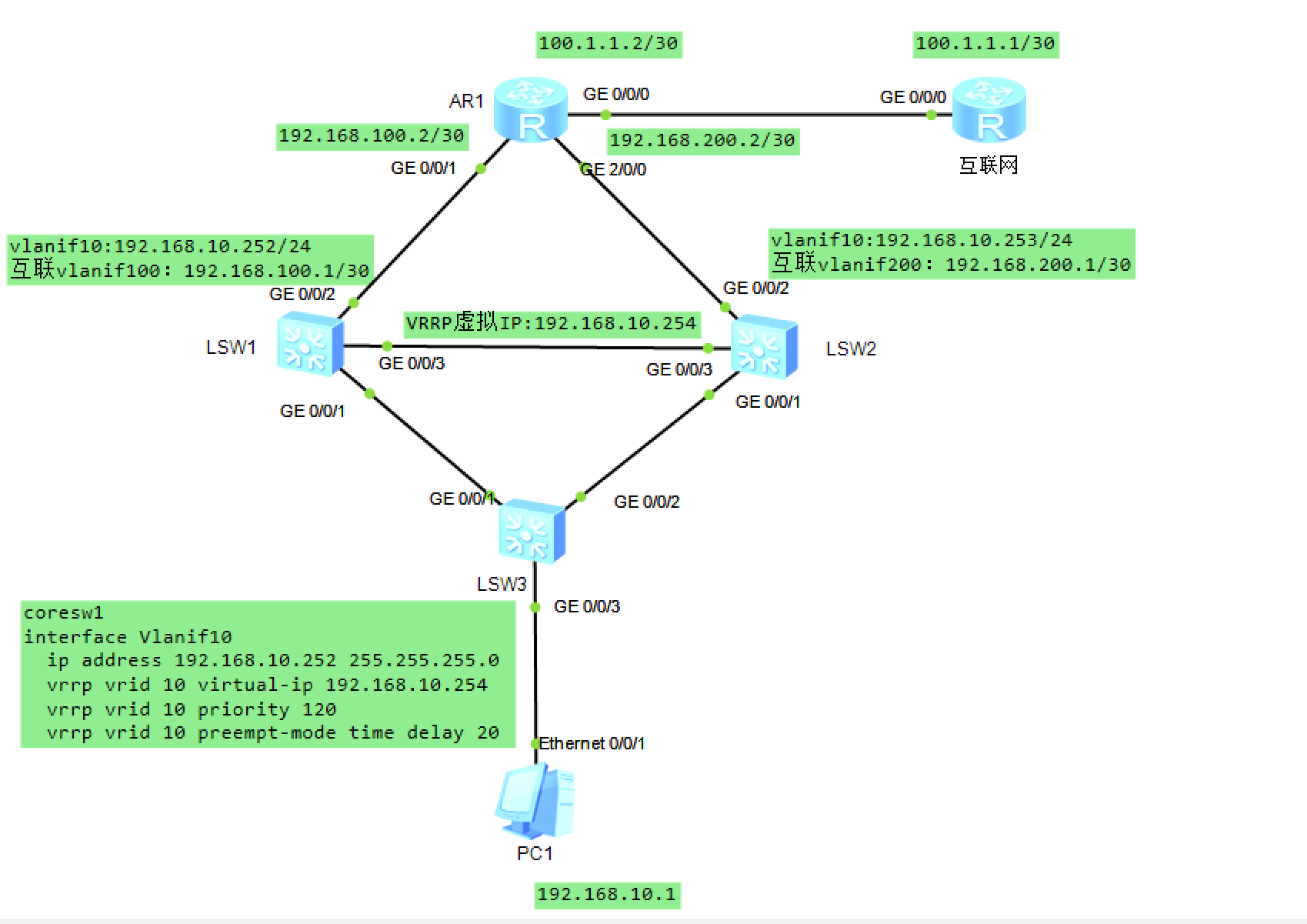
- 拓扑
- 配置接入交换机acsw
[acsw]interface g0/0/3
[acsw-GigabitEthernet0/0/3]port link-type access
[acsw-GigabitEthernet0/0/3]vlan 100
[acsw-vlan100]int g0/0/3
[acsw-GigabitEthernet0/0/3]port default vlan 10

[acsw]interface g0/0/1
[acsw-GigabitEthernet0/0/1]port link-type trunk
[acsw-GigabitEthernet0/0/1]port trunk allow-pass vlan all  //允许任何vlan通过
[acsw-GigabitEthernet0/0/1]int g0/0/2
[acsw-GigabitEthernet0/0/2]port link-type trunk
[acsw-GigabitEthernet0/0/2]port trunk allow-pass vlan all
- 配置核心交换机
# coresw1
[coresw1]int g0/0/1
[coresw1-GigabitEthernet0/0/1]port link-type trunk
[coresw1-GigabitEthernet0/0/1]port trunk allow-pass vlan all
[coresw1-GigabitEthernet0/0/1]int g0/0/3
[coresw1-GigabitEthernet0/0/3]port link-type trunk
[coresw1-GigabitEthernet0/0/3]port trunk allow-pass vlan all

[coresw1]vlan 10
[coresw1-vlan10]qu
[coresw1]vlan 100
[coresw1-vlan100]qu
[coresw1]interface g0/0/2
[coresw1-GigabitEthernet0/0/2]port link-type access
[coresw1-GigabitEthernet0/0/2]port default vlan 100
[coresw1-GigabitEthernet0/0/2]qu

# 配三层接口
[coresw1]interface Vlanif 10
[coresw1-Vlanif10]ip address 192.168.10.252 24
[coresw1-Vlanif10]qu
[coresw1]interface Vlanif 100
[coresw1-Vlanif100]ip address 192.168.100.1 30


------------------------------------------
# coresw2
[coresw2]interface g0/0/1
[coresw2-GigabitEthernet0/0/1]port link-type trunk
[coresw2-GigabitEthernet0/0/1]port trunk allow-pass vlan all
[coresw2-GigabitEthernet0/0/1]int g0/0/3
[coresw2-GigabitEthernet0/0/3]p l t
[coresw2-GigabitEthernet0/0/3]port trunk allow-pass vlan all
[coresw2-GigabitEthernet0/0/3]qu
[coresw2]vlan 10
[coresw2-vlan10]vlan 200
[coresw2-vlan200]qu
[coresw2]interface g0/0/2
[coresw2-GigabitEthernet0/0/2]port link-type access
[coresw2-GigabitEthernet0/0/2]port default vlan 200
[coresw2-GigabitEthernet0/0/2]qu
[coresw2]int Vlanif 10
[coresw2-Vlanif10]ip address 192.168.10.253 24
[coresw2-Vlanif10]int vlan 200
[coresw2-Vlanif200]ip address 192.168.200.1 30
- 配置VRRP
# coresw1 (master)
[coresw1]interface Vlanif 10
[coresw1-Vlanif10]vrrp vrid 10 virtual-ip 192.168.10.254
[coresw1-Vlanif10]vrrp vrid 10 priority 120
[coresw1-Vlanif10]vrrp vrid 10 preempt-mode timer delay 20
//缺省情况下,抢占模式已被激活,也可以配置为非抢占模式
//coresw1-Vlanif10]vrrp vrid 10 preempt-mode disable

# coresw2
[coresw2]interface Vlanif 10
[coresw2-Vlanif10]vrrp vrid 10 virtual-ip 192.168.10.254
//默认优先级是100 (backup),不需要配置抢占延迟,主服务挂掉后会直接使用备用机

# 此时使用PC1 ping 网关192.168.10.254是通的,实际上回应的是master 192.168.10.252

[coresw1]display vrrp
  Vlanif10 | Virtual Router 10
    State : Master
    Virtual IP : 192.168.10.254
    Master IP : 192.168.10.252
    PriorityRun : 120
    PriorityConfig : 120
    MasterPriority : 120
    Preempt : YES   Delay Time : 20 s

[coresw2]display vrrp
  Vlanif10 | Virtual Router 10
    State : Backup
    Virtual IP : 192.168.10.254
    Master IP : 192.168.10.252
    PriorityRun : 100
    PriorityConfig : 100
    MasterPriority : 120
    Preempt : YES   Delay Time : 0 s
- 配置路由
PC1(192.168.10.1) ping 互联网100.1.1.1
// 192.168.10.0 网段的流量要去100.1.1.0网段,下一跳扔给与AR1直连的端口
[coresw1]ip route-static 0.0.0.0 0 192.168.100.2
[coresw2]ip route-static 0.0.0.0 0 192.168.200.2
//互联网处理192.168.10.0 网段的流量,下一跳扔给与AR1直连的端口
[Huawei]ip route-static 192.168.10.0 24 100.1.1.2
//出口路由器AR1也需要配静态路由到192.168.10.0 网段
[AR1]ip route-static 192.168.10.0 24 192.168.100.1
[AR1]ip route-static 192.168.10.0 24 192.168.200.1

# 可以修改核心交换机的vrrp优先级,优先级高的为主master
[coresw1-Vlanif10]vrrp vrid 10 priority 90 (此时backup优先级为100,流量走192.168.10.253)
[coresw1-Vlanif10]vrrp vrid 10 priority 120
//等待抢占延迟20s,coresw1抢占优先,则流量又重新走192.168.10.252
- 跟踪上行接口
[coresw1]interface Vlanif 10
//跟踪上行端口,一旦端口宕掉,则vrrp优先级-30 ---> 90,则流量切换到backup(priority 100)
[coresw1-Vlanif10]vrrp vrid 10 track interface g0/0/2 reduced 30
[coresw1-Vlanif10]qu
[coresw1]interface g0/0/2
[coresw1-GigabitEthernet0/0/2]shutdown

[coresw1]display vrrp
  Vlanif10 | Virtual Router 10
    State : Backup
    Virtual IP : 192.168.10.254
    Master IP : 192.168.10.253
    PriorityRun : 90  //实际运行的优先级为90
    PriorityConfig : 120  //配置的优先级是120
05 浮动路由与BFD配置
-
拓扑
-
配置
# 配置各个设备的ip和接口ip
# 三台路由器通过OSPF互相学习路由(dainxin/liantong/network配置一致)
[dainxin]ospf 1
[dainxin-ospf-1]area 0
[dainxin-ospf-1-area-0.0.0.0]network 0.0.0.0 0.0.0.0
[dainxin-ospf-1-area-0.0.0.0]qu
[dainxin]display ospf peer brief   //可以查看

# 配置NAT,使用easy ip (使用出口ip+端口映射)
[router]acl 2000
[router-acl-basic-2000]rule 10 permit source 192.168.10.0 0.0.0.255
[router-acl-basic-2000]rule 20 permit source 192.168.20.0 0.0.0.255
[router]interface g3/0/0
[router-GigabitEthernet3/0/0]nat outbound 2000
[router-GigabitEthernet3/0/0]int g4/0/0
[router-GigabitEthernet4/0/0]nat outbound 2000

# 出口路由配置:配置两条默认路由,分别指向电信和联通
[router]ip route-static 0.0.0.0 0 12.1.1.2
[router]ip route-static 0.0.0.0 0 13.1.1.2
[router]display ip routing-table  //有两条路由,并且开销都是60
Route Flags: R - relay, D - download to fib
------------------------------------------------------------------------------
Routing Tables: Public
         Destinations : 17       Routes : 18

Destination/Mask    Proto   Pre  Cost      Flags NextHop         Interface

        0.0.0.0/0   Static  60   0          RD   12.1.1.2        GigabitEthernet
3/0/0
                    Static  60   0          RD   13.1.1.2        GigabitEthernet


# 基于源IP进行负载均衡(使用router AR2220型号,其他型号可能打不出load-balance)
[router]load-balance ?
  dst-ip       According to destination IP hash arithmetic
  dst-mac      According to destination MAC hash arithmetic
  src-dst-ip   According to source/destination IP hash arithmetic
  src-dst-mac  According to source/destination MAC hash arithmetic
  src-ip       According to source IP hash arithmetic
  src-mac      According to source MAC hash arithmetic
[router]load-balance src-ip


# 基础的浮动路由
# 修改其中一条路由的开销为100,则preference100的路由隐藏,当去向12.1.1.2的路由挂掉时,才启用去13.1.1.2的路由
[router]ip route-static 0.0.0.0 0 13.1.1.2 preference 100
[router]display ip routing-table
Route Flags: R - relay, D - download to fib
------------------------------------------------------------------------------
Routing Tables: Public
         Destinations : 17       Routes : 17

Destination/Mask    Proto   Pre  Cost      Flags NextHop         Interface

        0.0.0.0/0   Static  60   0          RD   12.1.1.2        GigabitEthernet
-
带
BFD的浮动路由
BFD(双向转发检测):用于检测系统设备之间的发生和接受两个方向的通信故障 -
在设备中加入一个二层交换机,dainxin服务器的端口shutdown; 此时router选择路由仍为去往12.1.1.2
# router(其实可以单边配置,但是模拟器不支持,所以需要在两个设备都配置BFD)
[router]bfd  //开启BFD
[router-bfd]qu
[router]bfd 1 ?
  bind  Bind type
  <cr>  Please press ENTER to execute command
[router]bfd 1 bind ?
  ldp-lsp     Information about LDP LSP
  mpls-te     Information about MPLS TE
  peer-ip     Set peer IP address
  static-lsp  Information about static LSP
[router]bfd 1 bind peer-ip 12.1.1.2 source-ip 12.1.1.1 ?
  auto  Auto-negotiate discriminator
  <cr>  Please press ENTER to execute command
[router]bfd 1 bind peer-ip 12.1.1.2 source-ip 12.1.1.1 auto
[router-bfd-session-1]commit


# dianxin
[dianxin]bfd
[dianxin-bfd]qu
[dianxin]bfd 1 bind peer-ip 12.1.1.1 source-ip 12.1.1.2 auto
// Info: The configuration succeeds, but BFD session cannot be created for the moment because the route cannot be found. (要先把shutdown接口打开)
[dianxin-bfd-session-1]int g0/0/0
[dianxin-GigabitEthernet0/0/0]undo shutdown
//[dianxin-GigabitEthernet0/0/0]bfd 1 bind peer-ip 12.1.1.1 source-ip 12.1.1.2 auto
//Error: The specified BFD configuration view has been created.
[dianxin]bfd 1
[dianxin-bfd-session-1]commit  //已经存在BFD配置,所以只要commit就行
[dianxin-bfd-session-1]qu

# BFD会不停检测两个地址之间的连通性 UP/DOWN
[dianxin]display bfd session all
--------------------------------------------------------------------------------
Local Remote     PeerIpAddr      State     Type        InterfaceName
--------------------------------------------------------------------------------

8192  0          12.1.1.1        Down      S_AUTO_PEER       -
--------------------------------------------------------------------------------
     Total UP/DOWN Session Number : 0/1


# router (之前配置的路由监视这个BFD,当bfd不通时,就删除该条路由)
[router]ip route-static 0.0.0.0 0 12.1.1.2 track bfd-session 1
Info: Succeeded in modifying route.

[dianxin-GigabitEthernet0/0/0]shutdown  //shutdown联通的接口

[router]display ip routing-table  //此时路由会切换为 0.0.0.0 0 13.1.1.2
Route Flags: R - relay, D - download to fib
------------------------------------------------------------------------------
Routing Tables: Public
         Destinations : 17       Routes : 17

Destination/Mask    Proto   Pre  Cost      Flags NextHop         Interface

        0.0.0.0/0   Static  100  0          RD   13.1.1.2
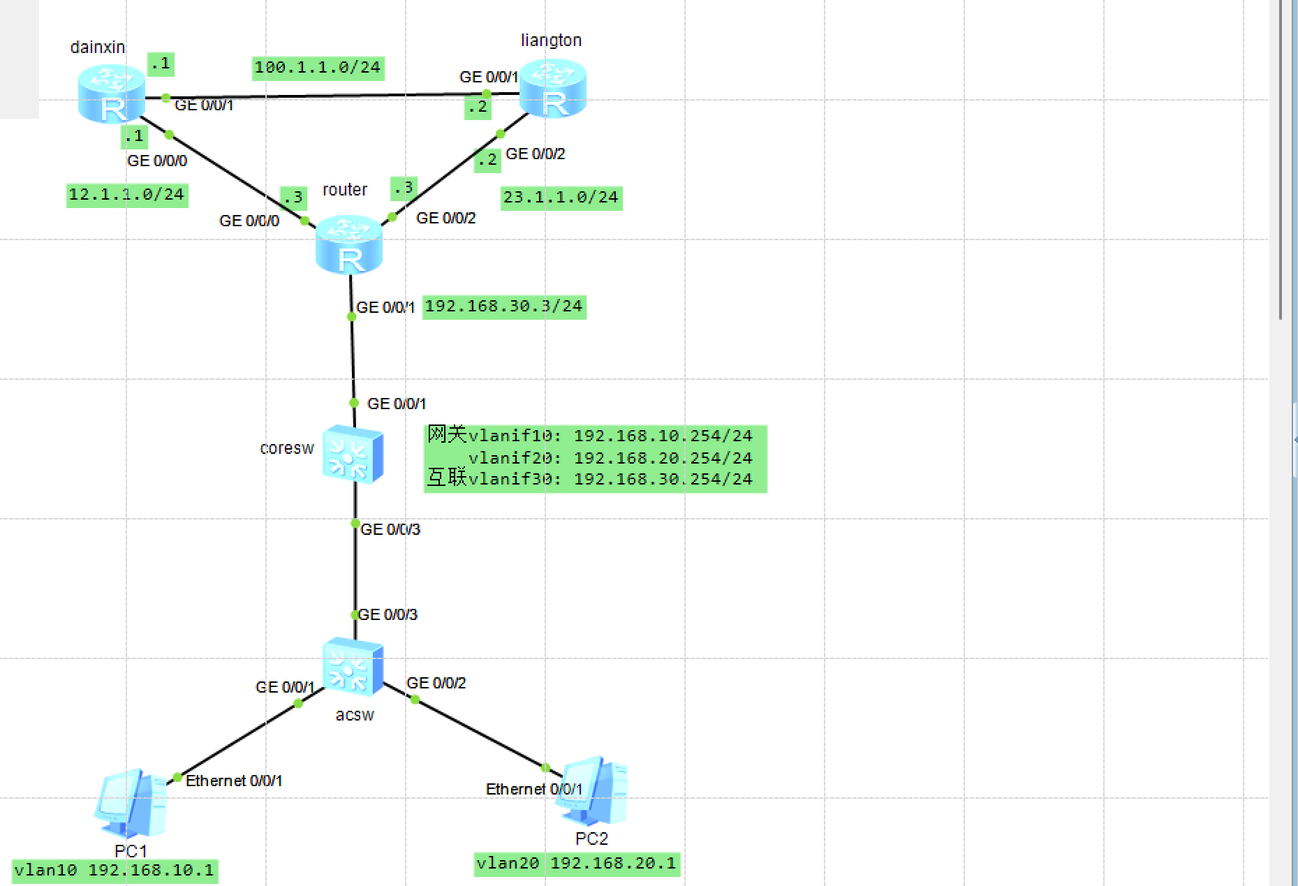
06-1 综合实验(HHCP+NAT+BFD+策略路由)
- 要求
1.Vlan配置与IP地址配置,实现跨Vlan通信
2.DHCP配置(全局基于接口)
3.路由配置:静态、默认、RIP/OSPF
4.ACL配置,Nat配置,策略路由配置
 4.1: 所有流量默认走电信,电信故障则走联通
 4.2:教学楼走电信,宿舍楼走联通
 4.3:访问电信走电信出口,访问联通走联通出口
- 拓扑
- 配置
- 内网部分
================ 接口交换机配置 ===================
[acsw]vlan 10
[acsw-vlan10]vlan 20
[acsw-vlan20]qu
[acsw]int g0/0/1
[acsw-GigabitEthernet0/0/1]port link-type access
[acsw-GigabitEthernet0/0/1]port default vlan 10
[acsw-GigabitEthernet0/0/1]int g0/0/2
[acsw-GigabitEthernet0/0/2]port link-type access
[acsw-GigabitEthernet0/0/2]port default vlan 20
[acsw-GigabitEthernet0/0/2]int g0/0/3
[acsw-GigabitEthernet0/0/3]port link-type trunk
[acsw-GigabitEthernet0/0/3]port trunk allow-pass vlan 10 20 //允许哪些vlan的流量通过,可以all

================ 核心交换机配置(网关+dhcp) ===================
//配置接口
[coresw]vlan batch 10 20 30  //批量创建vlan
[coresw]interface g0/0/3
[coresw-GigabitEthernet0/0/3]port link-type trunk
[coresw-GigabitEthernet0/0/3]port trunk allow-pass vlan 10 20

//配置网关
[coresw]int Vlanif 10
[coresw-Vlanif10]ip address 192.168.10.254 24
[coresw-Vlanif10]int vlanif 20
[coresw-Vlanif20]ip address 192.168.20.254 24

//配置DHCP
[coresw]dhcp enable
Info: The operation may take a few seconds. Please wait for a moment.done.
[coresw]ip pool 10
Info:It's successful to create an IP address pool.
[coresw-ip-pool-10]network 192.168.10.0 mask 24
[coresw-ip-pool-10]gateway-list 192.168.10.254
[coresw-ip-pool-10]dns-list 8.8.8.8
[coresw-ip-pool-10]lease day 3
[coresw-ip-pool-10]excluded-ip-address 192.168.10.2 192.168.10.253 //排除,只剩192.168.10.1
[coresw-ip-pool-10]q
[coresw]interface Vlanif 10  //接口应用DHCP
[coresw-Vlanif10]dhcp select global
[coresw]ip pool 20
Info:It's successful to create an IP address pool.
[coresw-ip-pool-20]network 192.168.20.0  mask 24
[coresw-ip-pool-20]gateway-list 192.168.20.254
[coresw-ip-pool-20]dns-list 114.114.114.114
[coresw-ip-pool-20]lease day 3
[coresw-ip-pool-20]excluded-ip-address 192.168.20.2 192.168.20.253
[coresw]int Vlanif 20
[coresw-Vlanif20]dhcp select global

//接口划入vlan,vlan设置ip,实现通信(ensp中交换机接口无法直接设置成ip)
[coresw-GigabitEthernet0/0/1]port link-type access
[coresw-GigabitEthernet0/0/1]port default vlan 30
[coresw-GigabitEthernet0/0/1]qu
[coresw]int Vlanif 30
[coresw-Vlanif30]ip add 192.168.30.254 24

# 以上是内网部分,PC1和PC2获得ip,并且可以互相ping通
# 解决路由器到PC的通路,学习到10.0和20.0网段

================ router配置 ===================
# 有三种方式配置
//静态路由
[router]ip route-static 192.168.10.0 255.255.255.0 192.168.30.254

//动态路由 RIP
[router]rip
[router-rip-1]version 2
[router-rip-1]network 192.168.30.0
[coresw]rip
[coresw-rip-1]ver 2
[coresw-rip-1]network 192.168.10.0
[coresw-rip-1]network 192.168.20.0
[coresw-rip-1]network 192.168.30.0

//动态路由 OSPF
[coresw]ospf 1
[coresw-ospf-1]area 0
[coresw-ospf-1-area-0.0.0.0]network 192.168.10.0 0.0.0.255
[coresw-ospf-1-area-0.0.0.0]network 192.168.20.0 0.0.0.255
[coresw-ospf-1-area-0.0.0.0]network 192.168.30.0 0.0.0.255
[router]ospf 1
[router-ospf-1]area 0
[router-ospf-1-area-0.0.0.0]network 192.168.30.0 0.0.0.255
- 网络出口配置
# 三个路由器之间的路由可以使用RIP
#dianxin和liantong互相宣告自己的网段(包括测试用的环回)

================ router配置 ===================
# 配置NAT地址转换(Easy IP)
[router]acl 2000
[router-acl-basic-2000]rule 10 permit source 192.168.10.0 0.0.0.255
[router-acl-basic-2000]rule 20 permit source 192.168.20.0 0.0.0.255
[router-acl-basic-2000]q
[router]interface g0/0/0
[router-GigabitEthernet0/0/0]nat outbound 2000
[router-GigabitEthernet0/0/0]int g0/0/2
[router-GigabitEthernet0/0/2]nat outbound 2000

# 此时PC ping dianxin是不通的,在coresw网关并没有到1.1.1.1的路由,在router中也没有
[coresw]ip route-static 0.0.0.0 0 192.168.30.3

[router]ip route-static 0.0.0.0 0 12.1.1.1 preference 50 //流量默认走电信
[router]ip route-static 0.0.0.0 0 23.1.1.2 //liantong 默认优先级60

# 配置BFD,监测dianxin,dainxin挂了走liantong
[router]bfd
[router-bfd]q
[router]bfd dianxin bind peer-ip 12.1.1.1 source-ip 12.1.1.3 auto
...
[dianxin]bfd dianxin bind peer-ip 12.1.1.3 source-ip 12.1.1.1 auto
[dianxin]display bfd session all //查看bfd状态

# 在出口路由跟踪,正常走dianxin,不正常删掉默认路由
[router]ip route-static 0.0.0.0 0 12.1.1.1 preference 50 track bfd-session dianxin  //监测dianxin
Info: Succeeded in modifying route.
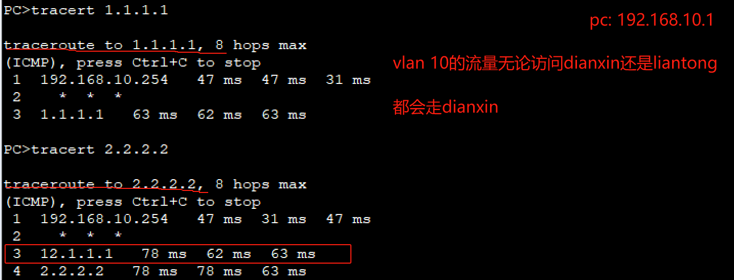
- 流量默认都走dianxin
- 模拟dianxin挂了,则流量走liangton
- 策略路由
//先删掉之前配置的默认路由
[router]undo ip route-static 0.0.0.0 0 23.1.1.2
[router]undo ip route-static 0.0.0.0 0 12.1.1.1

================ 策略路由配置 ===================
# 实现vlan10的流量走dianxin,vlan20的流量走liantong
//1.ACL匹配流量
# 4.2:教学楼走电信,宿舍楼走联通
[router]acl 2010
[router-acl-basic-2010]rule 10 permit source 192.168.10.0 0.0.0.255
[router-acl-basic-2010]acl 2020
[router-acl-basic-2020]rule 20 permit source 192.168.20.0 0.0.0.255
//2.流分类
[router]traffic classifier ?
  STRING<1-31>  Name of classifier
[router]traffic classifier zuo
[router-classifier-zuo]if-match acl 2010
[router-classifier-zuo]qu
[router]traffic classifier you
[router-classifier-you]if-match acl 2020
//3.流行为 (重定向流量)
[router]traffic behavior re-dianxin
[router-behavior-re-dianxin]redirect ip-nexthop 12.1.1.1
[router-behavior-re-dianxin]q
[router]traffic behavior re-liantong
[router-behavior-re-liantong]redirect ip-nexthop 23.1.1.2
//4.流策略 (把流分类和流行为绑定)
[router]traffic policy p
[router-trafficpolicy-p]classifier zuo behavior re-dianxin 	 //左边的流量扔给dianxin
[router-trafficpolicy-p]classifier you behavior re-liantong
//5.入接口应用策略路由
[router]interface g0/0/1
[router-GigabitEthernet0/0/1]traffic-policy ?
  STRING<1-31>  Name of Traffic policy
[router-GigabitEthernet0/0/1]traffic-policy p inbound
# 4.3:访问电信走电信出口,访问联通走联通出口
//基于目的的ip 策略路由,区别只在ACL的配置 (高级acl可以匹配目的ip)
eg: acl3000: rule 10 permit ip source any destination 1.1.1.0 0.0.0.255
//匹配任意地址源去往dianxin服务器1.1.1.1的流量
06-2 路由综合实验
- 拓扑
- 配置 (已配置各设备ip、端口)
- 宣告路由(OSPF/RIP)
# 配置RTP宣告网络

# R1
[R1]rip ?
  INTEGER<1-65535>  Process ID
  mib-binding       Mib-Binding a process
  vpn-instance      VPN instance
  <cr>              Please press ENTER to execute command
[R1]rip 1
//[R1-rip-1]network 100.1.1.0
//Error: The network address is invalid, and the specified address must be major-net address without any subnets.
[R1-rip-1]version 2
[R1-rip-1]network 100.0.0.0  //宣告网段 /8 的
[R1-rip-1]network 12.0.0.0
[R1-rip-1]network 13.0.0.0

[R2]rip
[R2-rip-1]version 2
[R2-rip-1]network 12.0.0.0
[R2-rip-1]network 23.0.0.0
[R3]rip
[R3-rip-1]version 2
[R3-rip-1]network 23.0.0.0
[R3-rip-1]network 13.0.0.0
[R3-rip-1]qu
[R3]display ip routing-table
//R3会学习到R2--->R1以及R1--->PC1的路由
# 也可以使用OSPF的方式宣告路由,与RIP不同,它需要网段+反掩码
//[R1]undo rip 1
//Warning: The RIP process will be deleted. Continue?[Y/N]y
[R1]ospf 1
[R1-ospf-1]area 0
[R1-ospf-1-area-0.0.0.0]network 100.1.1.0 0.0.0.255
[R1-ospf-1-area-0.0.0.0]network 12.1.1.0 0.0.0.3
[R1-ospf-1-area-0.0.0.0]network 13.1.1.0 0.0.0.3
[R1-ospf-1-area-0.0.0.0]qu

[R1]display ospf peer brief  //显示学习到的非直连路由

	 OSPF Process 1 with Router ID 100.1.1.254
		  Peer Statistic Information
 ----------------------------------------------------------------------------
 Area Id          Interface                        Neighbor id      State
 0.0.0.0          GigabitEthernet0/0/1             12.1.1.2         Full
 0.0.0.0          GigabitEthernet0/0/2             34.1.1.1         Full
 ----------------------------------------------------------------------------
- 配置BGP
# R3:属于 BGP100,对端属于BGP200
[R3]bgp 100
[R3-bgp]peer 34.1.1.2 as-number 200

# R4:属于 BGP200,两端连接R3属于BGP100,R5属于BGP200
[R4]bgp 200
[R4-bgp]peer 34.1.1.1 as-number 100
[R4-bgp]peer 45.1.1.2 as-number 200

[R4]display bgp peer //查看已建立的BGP

 BGP local router ID : 34.1.1.2
 Local AS number : 200
 Total number of peers : 2		  Peers in established state : 2

  Peer            V          AS  MsgRcvd  MsgSent  OutQ  Up/Down       State Pre
fRcv

  34.1.1.1        4         100       14       15     0 00:12:35 Established
   0
  45.1.1.2        4         200        4        4     0 00:01:50 Established
   1


# R5
[R5]bgp 200
[R5-bgp]peer 45.1.1.1 as-number 200

------------------------------------------------------
# 配置BGP后,还需要手动宣告路由
[R5]bgp 200
[R5-bgp]ipv4-family unicast
[R5-bgp-af-ipv4]network 200.1.1.0 24

# 此时R4可以学习到200的路由(通过IBGP)
[R4]display ip routing-table
0/0/1 200.1.1.0/24  IBGP    255  0          RD   45.1.1.2        GigabitEthernet

# R3和R4都学到了200的路由,但此时PC1和PC2不互通,没有对方的路由
- R3通过BGP学到的路由需要引入到OSPF中
# R3的OSPF引入BGP
[R3]ospf 1
[R3-ospf-1]import-route bgp
# 此时R1可以学习到200的路由

# R3的BGP引入OSPF
[R3]bgp 100
[R3-bgp]import-route ospf 1

----------------------------------------------

# 此时R4可以学习到100的路由(通过EBGP)
[R4]display ip routing-table
0/0/1
      100.1.1.0/24  EBGP    255  2           D   34.1.1.1        GigabitEthernet


# R5虽然学到BGP,但它没有到34.1.1.1的路由,所以不可达,因此不会将100加入路由
[R5]display bgp routing-table

 BGP Local router ID is 200.1.1.254
 Status codes: * - valid, > - best, d - damped,
               h - history,  i - internal, s - suppressed, S - Stale
               Origin : i - IGP, e - EGP, ? - incomplete


 Total Number of Routes: 5
      Network            NextHop        MED        LocPrf    PrefVal Path/Ogn

   i  12.1.1.0/30        34.1.1.1        2          100        0      100?
   i  13.1.1.0/30        34.1.1.1        0          100        0      100?
   i  23.1.1.0/30        34.1.1.1        0          100        0      100?
   i  100.1.1.0/24       34.1.1.1        2          100        0      100?
 *>   200.1.1.0          0.0.0.0         0                     0      i

##### 第一种方法:配置静态路由,告诉R5下一条走R4,然后R5的路由表可以学习到100、12、13、23等网段
[R5]ip route-static 34.1.1.0 30 45.1.1.1
[R5]display ip routing-table
##### 第二种方法:R4配置
//[R5]undo ip route-static 34.1.1.0 30 45.1.1.1
[R4]bgp 200
[R4-bgp]peer 45.1.1.2 next-hop-local   //对R5宣告下一跳是自己

# R5和R4直连,它去寻找的下一跳变成45.1.1.1
[R5]display bgp routing-table

 BGP Local router ID is 200.1.1.254
 Status codes: * - valid, > - best, d - damped,
               h - history,  i - internal, s - suppressed, S - Stale
               Origin : i - IGP, e - EGP, ? - incomplete


 Total Number of Routes: 5
      Network            NextHop        MED        LocPrf    PrefVal Path/Ogn

 *>i  12.1.1.0/30        45.1.1.1        2          100        0      100?
 *>i  13.1.1.0/30        45.1.1.1        0          100        0      100?
 *>i  23.1.1.0/30        45.1.1.1        0          100        0      100?
 *>i  100.1.1.0/24       45.1.1.1        2          100        0      100?
 *>   200.1.1.0          0.0.0.0         0                     0      i

# R5可以学到100的路由,此时PC1和PC2可以ping通
07 IPSec
- IPSec不是一个单独的协议,它通过AH和ESP这两个安全协议来实现IP数据报文的安全传送
- IKE协议提供秘钥协商,建立和维护安全联盟SA等服务
- 配置实验
- 拓扑
// 先把网络配通: 默认路由+acl [R1+R2]
[R1]ip route-static 0.0.0.0 0 100.1.1.2
[R1]acl 2000
[R1-acl-basic-2000]rule 10 permit source 192.168.10.0 0.0.0.255
[R1-acl-basic-2000]int g0/0/1
[R1-GigabitEthernet0/0/1]nat outbound 2000

# 配置IPSec
//1.定义需要的流量
[R1]acl 3000
[R1-acl-adv-3000]rule 10 permit ip source 192.168.10.0 0.0.0.255 destination 192
.168.20.0 0.0.0.255

[R2]acl 3000
[R2-acl-adv-3000]rule 10 permit ip source 192.168.20.0 0.0.0.255 destination 192
.168.10.0 0.0.0.255
# acl 2000是内部去访问互联网;acl 3000是打通路径,需要做加密等...

//2.配置IPSec提示(认证算法、加密算法) [R1 cd +R2 bj]
[R1]ipsec proposal cd
[R1-ipsec-proposal-cd]esp authentication-algorithm md5
[R1-ipsec-proposal-cd]esp encryption-algorithm des
- IPSec手动方式安全策略
//3.IPSec手动方式安全策略 [R1+R2]
[R1]ipsec policy chengdu ?
  INTEGER<1-10000>  The sequence number of IPSec policy
  shared            Shared
[R1]ipsec policy chengdu 10 manual  //手工manual
[R1-ipsec-policy-manual-chengdu-10]security acl 3000  //要保护的流量
[R1-ipsec-policy-manual-chengdu-10]proposal cd  //刚才配置的提议
[R1-ipsec-policy-manual-chengdu-10]tunnel local 100.1.1.1
[R1-ipsec-policy-manual-chengdu-10]tunnel remote 200.1.1.1
[R1-ipsec-policy-manual-chengdu-10]sa spi inbound esp 54321  //序号
[R1-ipsec-policy-manual-chengdu-10]sa string-key inbound esp cipher summer //密码
[R1-ipsec-policy-manual-chengdu-10]sa spi outbound esp 12345
[R1-ipsec-policy-manual-chengdu-10]sa string-key outbound esp cipher summer
# 对端 esp相反,一个进一个出
[R2]ipsec policy beijing 10 manual
[R2-ipsec-policy-manual-beijing-10]security acl 3000
[R2-ipsec-policy-manual-beijing-10]proposal bj
[R2-ipsec-policy-manual-beijing-10]tunnel local 200.1.1.1
[R2-ipsec-policy-manual-beijing-10]tunnel remote 100.1.1.1
[R2-ipsec-policy-manual-beijing-10]sa spi inbound esp 12345  //对端的outbound是我的inbound
[R2-ipsec-policy-manual-beijing-10]sa string-key inbound esp cipher summer
[R2-ipsec-policy-manual-beijing-10]sa spi outbound esp 54321
[R2-ipsec-policy-manual-beijing-10]sa string-key outbound esp cipher summer

//4.在出接口应用IPSec [R1+R2]
[R1]int g0/0/1
[R1-GigabitEthernet0/0/1]ipsec policy chengdu
# 配置了IPSec之后,PC1和PC2仍无法通信?
原因是最开始配置的acl2000,应用在端口g0/0/1,将内网出去的数据都转换成公网ip 100.1.1.1,但我们配置的隧道是应用acl3000
[R1]display cu | b ac  //ACL的匹配是从上到下,一旦匹配到就结束
...
acl number 2000
 rule 10 permit source 192.168.10.0 0.0.0.255
#
acl number 3000
 rule 10 permit ip source 192.168.10.0 0.0.0.255 destination 192.168.20.0 0.0.0.255
//[R1]undo acl 2000
//Error: The designated ACL group is in use, so it cannot be deleted!
[R1-GigabitEthernet0/0/1]undo nat outbound 2000
[R1-GigabitEthernet0/0/1]qu
[R1]undo acl 2000
[R1]acl 3001	//重新配置一个ACL
[R1-acl-adv-3001]rule 10 deny ip source 192.168.10.0 0.0.0.255 destination 192.168.20.0 0.0.0.255  //拒绝10.0~20.0的网段,这部分走我们的IPSec隧道
[R1-acl-adv-3001]rule 20
[R1-acl-adv-3001]rule 20 permit ip //放行其他的流量
[R1]int g0/0/1
[R1-GigabitEthernet0/0/1]nat outbound 3001
PC1 ping PC2,数据是加密的:
2. IPSec通过IKE动态建立隧道(暂时没看,记得补齐)
08 防火墙配置
- 拓扑
- 其中USG6000V需要导入镜像才能用
- 问题:无法运行防火墙
根据教程修改window设置中的防火墙,但仍无法解决问题…所以直接关闭防火墙,实验结束再打开
- 配置
1.内网主机PC1可以主动访问Internet,但Internet无法主动访问PC1
2.出口防火墙进行Nat,NAT公网地址池100.1.1.10~100.1.1.20
3.Internet可以通过公网地址100.1.1.100/24访问目的地址为192.168.2.100/24的内部web服务
# 省略设备的ip配置
============= 防火墙配置,开启时需要输入用户名密码 (admin/Admin@1234) ==============
[Firewall]firewall zone trust
[Firewall-zone-trust]add interface g1/0/1
[Firewall-zone-trust]qu
[Firewall]firewall zone untrust
[Firewall-zone-untrust]add interface g1/0/3
[Firewall-zone-untrust]qu
[Firewall]firewall zone dmz
[Firewall-zone-dmz]add interface g1/0/2
[Firewall-zone-dmz]qu

# 配置安全策略
[Firewall]security-policy
[Firewall-policy-security]rule name trust_to_untrust
[Firewall-policy-security-rule-trust_to_untrust]source-zone trust
[Firewall-policy-security-rule-trust_to_untrust]destination-zone untrust
[Firewall-policy-security-rule-trust_to_untrust]source-address 192.168.1.0 24
[Firewall-policy-security-rule-trust_to_untrust]destination-address any
[Firewall-policy-security-rule-trust_to_untrust]action ?
  deny    Indicate the rule action deny
  permit  Indicate the rule action permit
[Firewall-policy-security-rule-trust_to_untrust]action permit
[Firewall-policy-security-rule-trust_to_untrust]qu
[Firewall-policy-security]

# 配置NAT地址池,开启端口转换
[Firewall]nat address-group addressgroup1
[Firewall-address-group-addressgroup1]mode pat
[Firewall-address-group-addressgroup1]section 0 100.1.1.10 100.1.1.20
[Firewall-address-group-addressgroup1]qu

# 配置NAT策略,实现私网指定网段访问internet时自动进行源地址转换
[Firewall]nat-policy
[Firewall-policy-nat]rule name policy_nat1
[Firewall-policy-nat-rule-policy_nat1]source-zone trust
[Firewall-policy-nat-rule-policy_nat1]destination-zone untrust
[Firewall-policy-nat-rule-policy_nat1]source-address 192.168.1.0 24
[Firewall-policy-nat-rule-policy_nat1]destination-address any
[Firewall-policy-nat-rule-policy_nat1]action source-nat address-group addressgro
up1
[Firewall-policy-nat-rule-policy_nat1]qu
[Firewall-policy-nat]qu
- PC ping network,可以看到端口地址转换
# 放行trust到dmz的流量 (防火墙默认端口之间都是deny的)
[Firewall]security-policy
[Firewall-policy-security]rule name trust_to_dmz
[Firewall-policy-security-rule-trust_to_dmz]source-zone trust
[Firewall-policy-security-rule-trust_to_dmz]destination-zone dmz
[Firewall-policy-security-rule-trust_to_dmz]action permit

# 内网服务器的web服务映射到公网
[Firewall]nat server protocol tcp global 100.1.1.100 80 inside 192.168.2.100 80

[Firewall-policy-security]rule name untrust_to_dmz
[Firewall-policy-security-rule-untrust_to_dmz]source-zone untrust
[Firewall-policy-security-rule-untrust_to_dmz]destination-zone dmz
[Firewall-policy-security-rule-untrust_to_dmz]destination-address 192.168.2.100 24
[Firewall-policy-security-rule-untrust_to_dmz]action permit
- Internet访问内部web服务器
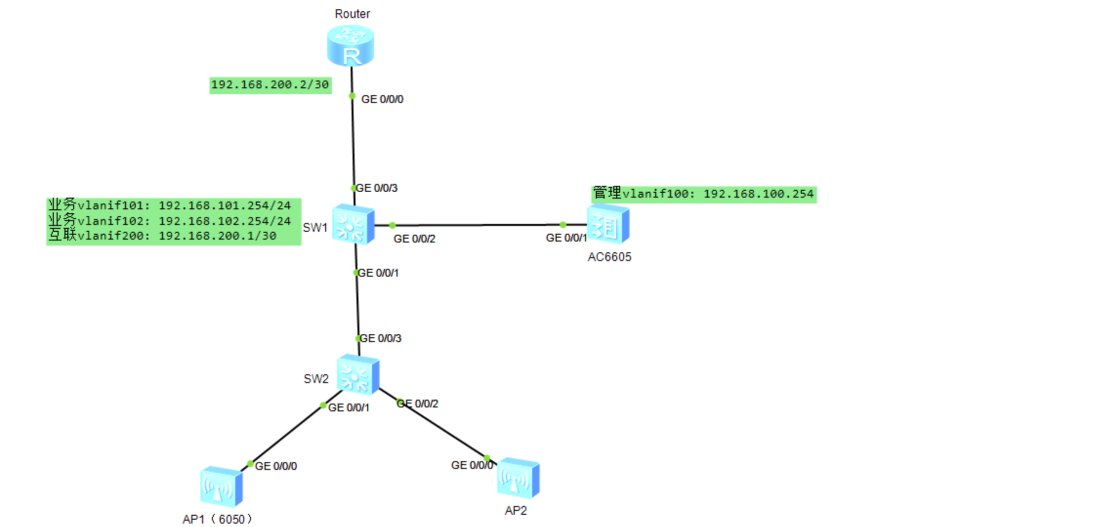
09 无线WLAN
- 拓扑
- 需求
1、配置隧道转发模式,完成AP上线,内部办公用户(VLAN101)能通过无线上网
2、访客(VLAN102)能通过无线上网,配置为直接转发模式
3、管理VLAN 100,业务VLAN 101和102,VLAN 101为内部用户提供上网服务(SSID:work) , VLAN 102为访客提供上网服务(SSID: guest)
AP通过AC DHCP自动获取IP 192.168.100.0/24地址段的地址,用户通过SW1 DHCP自动分配对应网段的地址。
- 配置
================ Router ================
[Router]interface g0/0/0
[Router-GigabitEthernet0/0/0]ip add 192.168.200.2 30
# 跟路由直连的接口是g0/0/3,属于vlan200
[Router]ip route-static 192.168.101.0 24 192.168.200.1
[Router]ip route-static 192.168.102.0 24 192.168.200.1


================ SW1 ================
[SW1]vlan batch 101 102 200 100
Info: This operation may take a few seconds. Please wait for a moment...done.
[SW1]interface g0/0/3
[SW1-GigabitEthernet0/0/3]port link-type access
[SW1-GigabitEthernet0/0/3]port default vlan 200
[SW1-GigabitEthernet0/0/3]int g0/0/2
[SW1-GigabitEthernet0/0/2]port link-type trunk
[SW1-GigabitEthernet0/0/2]port trunk allow-pass vlan all
[SW1-GigabitEthernet0/0/2]int g0/0/1
[SW1-GigabitEthernet0/0/1]port link-type trunk
[SW1-GigabitEthernet0/0/1]port trunk allow-pass vlan 100
(下行口通过隧道模式访问,只需要通过vlan100通过即可)

[SW1]interface Vlanif 101
[SW1-Vlanif101]ip add 192.168.101.254 24
[SW1-Vlanif101]qu
[SW1]interface Vlanif 102
[SW1-Vlanif102]ip add 192.168.102.254 24
[SW1-Vlanif102]int vlan 200
[SW1-Vlanif200]ip add 192.168.200.1 30

# 把SW1配置成DHCP服务器,为终端分配ip地址
[SW1]dhcp enable
[SW1]int Vlanif 101
[SW1-Vlanif101]dhcp select interface  //基于接口配置DHCP
[SW1-Vlanif101]qu
[SW1]int Vlanif 102
[SW1-Vlanif102]dhcp select interface
[SW1-Vlanif102]qu

================ SW2 ================
[SW2]vlan 100
[SW2-vlan100]qu
[SW2]int g0/0/3
[SW2-GigabitEthernet0/0/3]port link-type trunk
# 隧道模式,仅允许管理vlan100通过即可,数据都会被vlan100封装,转发到AC再拆分
[SW2-GigabitEthernet0/0/3]port trunk allow-pass vlan 100
# (两个AP的配置本质上是一样的,所以这里只配一个)
[SW2-GigabitEthernet0/0/3]int g0/0/1
[SW2-GigabitEthernet0/0/1]port link-type trunk
[SW2-GigabitEthernet0/0/1]port trunk allow-pass vlan 100
# 交换机的该端口,收到不带vlanid的数据包时,为数据包打上一个vlanid=100的tag (缺省)
[SW2-GigabitEthernet0/0/1]port trunk pvid vlan 100
================ 配置无线控制器AC ================
[AC6605]vlan batch 100 101 102 //100是管路vlan,101和102是业务vlan
[AC6605]int g0/0/1
[AC6605-GigabitEthernet0/0/1]port link-type trunk
[AC6605-GigabitEthernet0/0/1]port trunk allow-pass vlan all
[AC6605-GigabitEthernet0/0/1]qu
[AC6605]int Vlanif 100
[AC6605-Vlanif100]ip add 192.168.100.254 24

# 开启DHCP,为AP分配ip地址
[AC6605]dhcp enable
[AC6605]int Vlanif 100
[AC6605-Vlanif100]dhcp select interface


================ 在AC上配置AP上线 ================
# 1. 创建域管理模版,并配置国家代码
[AC6605]wlan
[AC6605-wlan-view]regulatory-domain-profile name china
[AC6605-wlan-regulate-domain-china]country-code CN //默认
Info: The current country code is same with the input country code.
[AC6605-wlan-regulate-domain-china]qu

# 2. 创建AP组,并引用特定的域管理模版
[AC6605-wlan-view]ap-group name jiaoxue  //AP组可以集中管理多个AP
Info: This operation may take a few seconds. Please wait for a moment.done.
[AC6605-wlan-ap-group-jiaoxue]regulatory-domain-profile china //引用模板
Warning: Modifying the country code will clear channel, power and antenna gain c
onfigurations of the radio and reset the AP. Continue?[Y/N]:y

# 3. 配置CAPWAP隧道源接口或者源地址
//AC和AP之间建立隧道,传递AC控制信息和一些数据
[AC6605]capwap source interface Vlanif 100

# 4. 配置AP设备入网认证
[AC6605]wlan
[AC6605-wlan-view]ap auth-mode ?   //ap认证模式
  mac-auth  MAC authenticated mode, default authenticated mode
  no-auth   No authenticated mode
  sn-auth   SN authenticated mode
[AC6605-wlan-view]ap auth-mode mac-auth
[AC6605-wlan-view]ap-id 1 ap-mac ?
  MAC_ADDR<XXXX-XXXX-XXXX>  AP MAC address
[AC6605-wlan-view]ap-id 1 ap-mac 00e0-fcc8-3030  //查看AP1的接口mac
[AC6605-wlan-ap-1]ap-name JX001  //AP1命名
[AC6605-wlan-ap-1]ap-group jiaoxue  //AP1加入AP组
Warning: This operation may cause AP reset. If the country code changes, it will
 clear channel, power and antenna gain configurations of the radio, Whether to c
ontinue? [Y/N]:y
Info: This operation may take a few seconds. Please wait for a moment.. done.

# 5. 验证
[AC6605]display ap all
Info: This operation may take a few seconds. Please wait for a moment.done.
Total AP information:
nor  : normal          [1]
--------------------------------------------------------------------------------
ID   MAC            Name  Group   IP              Type            State STA Upti
me
--------------------------------------------------------------------------------
1    00e0-fcc8-3030 JX001 jiaoxue 192.168.100.160 AP8130DN-W      nor   0   28S
--------------------------------------------------------------------------------

# ID为1,名称为JX001,属于组 jiaoxue,MAC是00e0-fcc8-3030,IP地址是192.168.100.160的AP,
设备型号是 AP6050DN,状态是nor (normal,正常),即AP完成上线。
- AP完成上线后,名字被自动修改为JX001,无需手动
================ 一. 配置AC无线业务(work),配置完成后会自动下发到对应AP ================
# 1.配置用户认证方式
[AC6605]wlan //进入wlan配置模式
[AC6605-wlan-view]security-profile name sec_work  //安全模板,名称为sec_work
//WPA-WPA2方式认证,PKS 表示预共享密码,简单理解就是通过密码方式认证,密码是a1234567,加密算法采用AES
[AC6605-wlan-sec-prof-sec_work]security wpa-wpa2 psk pass-phrase a1234567 aes
[AC6605-wlan-sec-prof-sec_work]qu

# 2.配置ssid模板
[AC6605-wlan-view]ssid-profile name profile_work //ssid模板,名称为profile_work
[AC6605-wlan-ssid-prof-profile_work]ssid work //ssid名称是work
Info: This operation may take a few seconds, please wait.done.

# 3.配置VAP模版,设置为隧道模式,配置用户VLAN101,并绑定安全模版、SSID模版
[AC6605-wlan-view]vap-profile name vap_work
[AC6605-wlan-vap-prof-vap_work]forward-mode tunnel
Info: This operation may take a few seconds, please wait.done.
//使用这个vap模板的用户服务vlan是101,即所有连接到vap_work这个VAP的用户被划分到VLAN 101
[AC6605-wlan-vap-prof-vap_work]service-vlan vlan-id 101
Info: This operation may take a few seconds, please wait.done.
[AC6605-wlan-vap-prof-vap_work]security-profile sec_work //调用安全模板sec_work
Info: This operation may take a few seconds, please wait.done.
[AC6605-wlan-vap-prof-vap_work]ssid-profile profile_work //调用ssid模板profile_work

# 4.在AP组中绑定vap模板
[AC6605-wlan-view]ap-group name jiaoxue
//在AP组中,将指定的VAP模板引用到射频,一般redio 0表示2.4GHz,radio 1表示5GHz 。
[AC6605-wlan-ap-group-jiaoxue]vap-profile vap_work wlan 1 radio 0
Info: This operation may take a few seconds, please wait...done.
[AC6605-wlan-ap-group-jiaoxue]vap-profile vap_work wlan 1 radio 1
Info: This operation may take a few seconds, please wait...done.
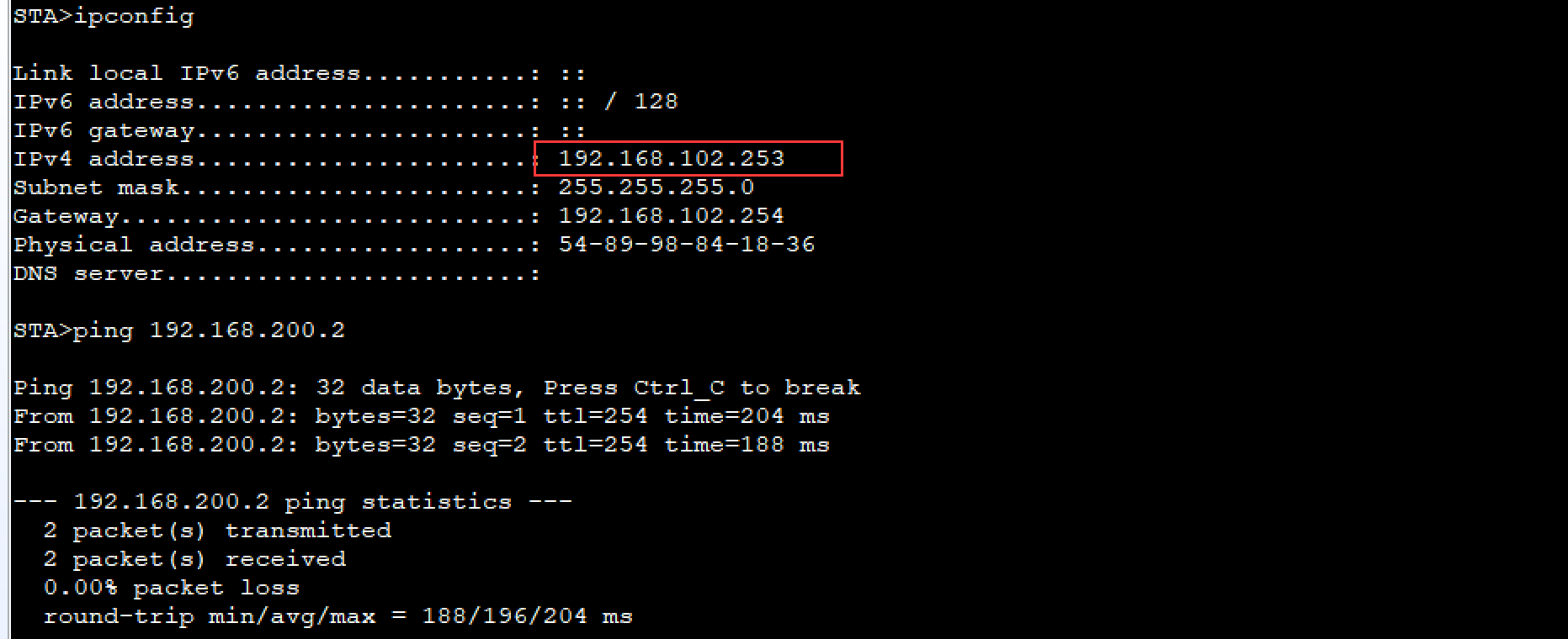
- 验证与测试
- 配置完成后,STA1可以正常连接
- 查看分配的IP地址,正常获取VLAN101的地址
- STA1可以ping通出口路由器Router
- AP1下的访客用户(SSID: guest)划分到VLAN 102,访客业务(VLAN 102)采用直接转发模式,需要进行如下配置:
# 直接转发,需要经过SW2和SW1
[SW1]interface g0/0/1
[SW1-GigabitEthernet0/0/1]port trunk allow-pass vlan 102 100

[SW2]vlan 102  //转发模式SW2还需要创建vlan102
[SW2-vlan102]int g0/0/1
[SW2-GigabitEthernet0/0/1]port trunk allow-pass vlan 100 102
[SW2-GigabitEthernet0/0/1]int g0/0/3
//放行管理vlan100和访客业务vlan102的流量
[SW2-GigabitEthernet0/0/3]port trunk allow-pass vlan 100 102
================ 二. 配置AC无线业务(guest),配置完成后会自动下发到对应AP ================
# 前面已经配置AC的上线,不需要重复配置
# 需要配置访客的AC,认证可以复用之前的sec_work
[AC6605]wlan
[AC6605-wlan-view]ssid-profile name profile_guest
[AC6605-wlan-ssid-prof-profile_guest]ssid guest
Info: This operation may take a few seconds, please wait.done.
[AC6605-wlan-ssid-prof-profile_guest]qu
[AC6605-wlan-view]vap-profile name vap_guest
[AC6605-wlan-vap-prof-vap_guest]forward-mode direct-forward  //采用直接转发
[AC6605-wlan-vap-prof-vap_guest]service-vlan vlan-id 102 //访客业务vlan 102
Info: This operation may take a few seconds, please wait.done.
[AC6605-wlan-vap-prof-vap_guest]security-profile sec_work //引用安全模板
Info: This operation may take a few seconds, please wait.done.
[AC6605-wlan-vap-prof-vap_guest]ssid-profile profile_guest //引用ssid模板
Info: This operation may take a few seconds, please wait.done.
[AC6605-wlan-vap-prof-vap_guest]qu
[AC6605-wlan-view]ap-group name jiaoxue
//jiaoxue 组中所有AP都开启一个叫 vap_guest的虚拟AP,并开启虚拟AP所有的射频卡
[AC6605-wlan-ap-group-jiaoxue]vap-profile vap_guest wlan 2 radio all
Info: This operation may take a few seconds, please wait...done.
- 测试STA连接
因为是直连的,因此在ping network时,数据不会经过AC,在AC的端口抓包看不到ping的icmp报文

